
Page 20: of Maritime Reporter Magazine (February 2013)
Cruise & Passenger Vessel
Read this page in Pdf, Flash or Html5 edition of February 2013 Maritime Reporter Magazine
 19
19
 21
21
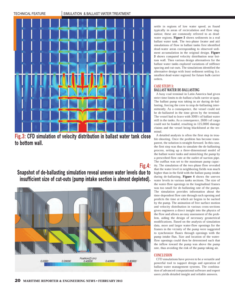
20 MARITIME REPORTER & ENGINEERING NEWS ? FEBRUARY 2013 TECHNICAL FEATURE SIMULATION & BALLAST WATER TREATMENT settle in regions of low water speed, as found typically in areas of recirculation and flow stag-nation; these are commonly referred to as dead-water regions. Figure 2 shows sediments in a real ballast water tank. The two-phase (water and air) simulations of flow in ballast tanks first identified dead-water areas corresponding to observed sedi-ment accumulation in the original design. Figure 3 shows computed velocity distribution near bot-tom wall. Then various design alternatives for the ballast water tanks explored variations of stiffener spacing and cut-outs. The simulations identified the alternative design with least sediment settling (i.e. smallest dead-water regions) for future bulk carrier orders. CASE STUDY 3: BALLAST WATER DE-BALLASTING A busy coal terminal in Latin America had given strict time limits to de-ballast a bulk carrier at quay. The ballast pump was taking in air during de-bal-lasting, forcing the crew to stop de-ballasting inter- mittently. As a consequence, the vessel could not be de-ballasted in the time given by the terminal. The vessel had to leave with 3000 t of ballast water still in the tanks. As a consequence, 2600 t of cargo could not be loaded, resulting in 125,000? damage claims and the vessel being blacklisted at the ter- minal.A detailed analysis is often the first step in trou- ble-shooting. Once the problem has become trans-parent, the solution is straight-forward. In this case, the first step was thus to simulate the de-ballasting process, setting up a three-dimensional model of the ballast water tanks and mimicking the pump by a prescribed flow rate at the outlet of suction pipe. The outflux was set to the maximum pump capac-ity. The simulation of the two-phase flow revealed that the water level in neighboring fields was much higher than in the field with the ballast pump intake during de-ballasting. Figure 4 shows the uneven water levels in various tanks sections. The size of the water-flow openings in the longitudinal frames was too small for de-ballasting rate of the pumps. The simulation provides information about the time-dependent flow rate through each opening and predicts the time at which air begins to be sucked by the pump. The animation of free surface motion and velocity distribution in various cross-sections gives engineers a direct insight into the physics of the flow and allows an easy assessment of the prob-lem, aiding the design of necessary geometrical modifications. Based on the analysis of simulation data, more and larger water-flow openings for the frames in the vicinity of the pump were suggested to synchronize fluxes through openings with the pump intake flux. Size and location of the water- flow openings could then be determined such that the inflow toward the pump was above the pump rate, thus avoiding the risk of the pump taking air. CONCLUSIONCFD simulations have proven to be a versatile and powerful tool to support design and operation of ballast water management systems. The combina- tion of advanced computational software and expert users yields detailed insight and reliable answers. Fig.3: CFD simulation of velocity distribution in ballast water tank close to bottom wall.Fig.4: Snapshot of de-ballasting simulation reveal uneven water levels due to insufficient size of cut-outs (pump intake section is almost depleted).MR #2 (18-25).indd 20MR #2 (18-25).indd 202/1/2013 9:47:16 AM2/1/2013 9:47:16 AM
