
Page 20: of Maritime Reporter Magazine (May 2017)
The Marine Propulsion Edition
Read this page in Pdf, Flash or Html5 edition of May 2017 Maritime Reporter Magazine
 19
19
 21
21
EYE ON DESIGN
Finite Element Strength
Analysis for ATB Load Box
The loading and response dynamics of an Articulated Tug & Barge (ATB) load box are complex. They typically require advanced ? nite element analysis meth- ods and procedures to design an ef? cient support structure to ensure a durable design and to facilitate meeting Class strength requirements. o study the dynamic response itself, typically by scantling increases, project, Viking employs a full breadth are modeled with a mesh size that cor- of the loads imparted on the material grade changes, addition of FE model including the original tug responds to the two elements between tug from the barge, a ? nite ele- brackets and panel breakers. structure, new load box, and any tran- transverse frames.
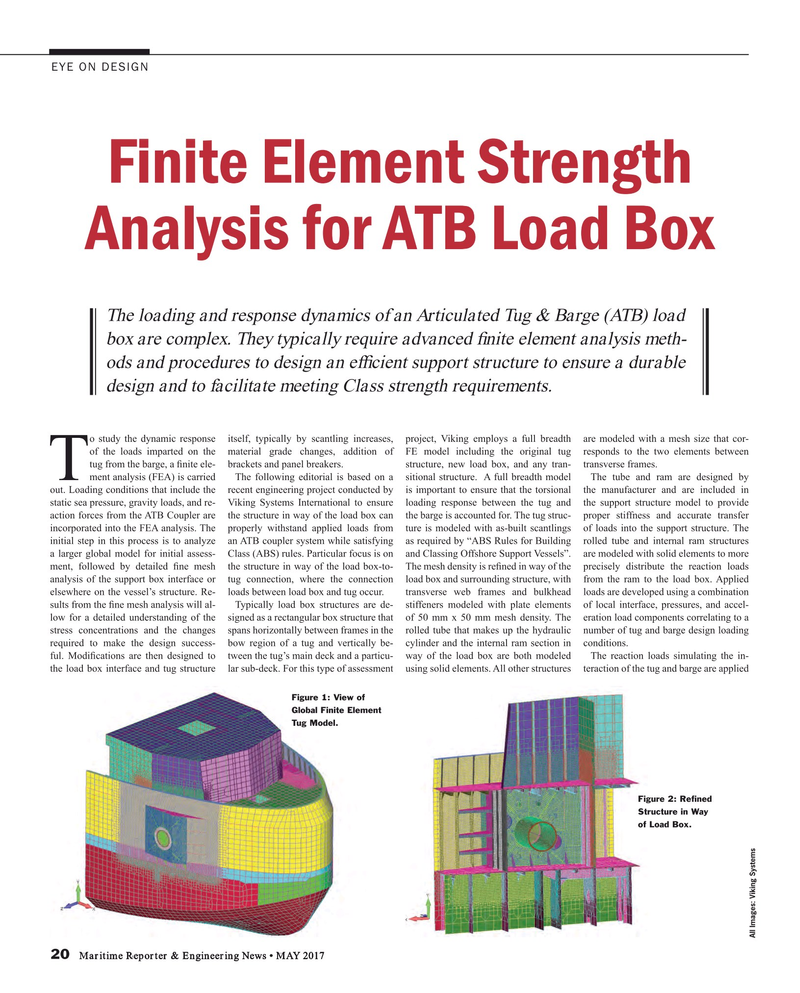
Tment analysis (FEA) is carried The following editorial is based on a sitional structure. A full breadth model The tube and ram are designed by out. Loading conditions that include the recent engineering project conducted by is important to ensure that the torsional the manufacturer and are included in static sea pressure, gravity loads, and re- Viking Systems International to ensure loading response between the tug and the support structure model to provide action forces from the ATB Coupler are the structure in way of the load box can the barge is accounted for. The tug struc- proper stiffness and accurate transfer incorporated into the FEA analysis. The properly withstand applied loads from ture is modeled with as-built scantlings of loads into the support structure. The initial step in this process is to analyze an ATB coupler system while satisfying as required by “ABS Rules for Building rolled tube and internal ram structures a larger global model for initial assess- Class (ABS) rules. Particular focus is on and Classing Offshore Support Vessels”. are modeled with solid elements to more ment, followed by detailed ? ne mesh the structure in way of the load box-to- The mesh density is re? ned in way of the precisely distribute the reaction loads analysis of the support box interface or tug connection, where the connection load box and surrounding structure, with from the ram to the load box. Applied elsewhere on the vessel’s structure. Re- loads between load box and tug occur. transverse web frames and bulkhead loads are developed using a combination sults from the ? ne mesh analysis will al- Typically load box structures are de- stiffeners modeled with plate elements of local interface, pressures, and accel- low for a detailed understanding of the signed as a rectangular box structure that of 50 mm x 50 mm mesh density. The eration load components correlating to a stress concentrations and the changes spans horizontally between frames in the rolled tube that makes up the hydraulic number of tug and barge design loading required to make the design success- bow region of a tug and vertically be- cylinder and the internal ram section in conditions. ful. Modi? cations are then designed to tween the tug’s main deck and a particu- way of the load box are both modeled The reaction loads simulating the in- the load box interface and tug structure lar sub-deck. For this type of assessment using solid elements. All other structures teraction of the tug and barge are applied
Figure 1: View of
Global Finite Element
Tug Model.
Figure 2: Re? ned
Structure in Way of Load Box.
All Images: Viking Systems 20 Maritime Reporter & Engineering News • MAY 2017
MR #5 (18-25).indd 20 MR #5 (18-25).indd 20 5/3/2017 8:00:40 PM5/3/2017 8:00:40 PM
