Lasers
-
- CWDM for the Subsea Market Marine Technology, Mar 2016 #19
Originally developed for the Metro Telecom market, CWDM (Coarse Wavelength Division Multiplexing) technology has become ubiquitous in all telecom markets as well as the subsea market.
CWDM is a cost-effective and technology-efficient way to multiplex a number of signals on one fiber. There are a number of wavelength multiplexing techniques that can be utilized, depending on the number of wavelengths. Standard WDM (Wavelength Division Multiplexing) utilizes either two, three or in some instances four wavelengths using standard lasers. CWDM technology can multiplex up to 18 individual wavelengths onto a single fiber. DWDM (Dense Wavelength Division Multiplexing) can typically multiplex 40 or 80 wavelengths on a single fiber. More elaborate DWDM techniques allow even higher density wavelength multiplexing. The most common method for wavelength multiplexing in the subsea market is CWDM where lower cost lasers and laser drivers can be used while maintaining the ability to multiplex a wide variety and quantity of unidirectional and bidirectional signals.While CWDM technology is available for both single-mode and multimode systems, single-mode is the most common type as it offers increased multiplexing and distance capabilities. Most CWDM systems area available in increments of 4 wavelengths or channels (from 4 to 16 wavelengths). Figure 1 illustrates the CWDM wavelength plan. The first or lowest wavelength is 1270nm while the longest wavelength is 1610nm in increments of 20nm. While some systems are available with 18 wavelength, most utilize up to 16 wavelengths leaving the middle two (1430 and 1450nm) as a guard band when combining the lower 8 with the upper 8 wavelengths.There are three unique elements in a CWDM system – Wavelength- specific laser, CWDM multiplexer and CWDM demultiplexer.Lasers – Lasers used in CWDM systems are the type known as DFB (Distributed FeedBack) lasers. The main characteristic of these lasers that is important in CWDM systems is the narrow spectral width, or wavelength spread of the laser’s light. The more common laser used in many fiber systems is the FP or Fabry-Perot. These lasers have a spectral width on the order of 3-6 nm while the DFB lasers have a spectral width of 0.1 nm or less, making them perfect for use in CWDM and DWDM (Dense Wavelength Division Multiplex) systems. As the curve in Figure 1 illustrates, these DFB lasers for CWDM systems range in wavelengths from 1270nm to 1610nm, in increments of 20nm. One of the advantages of CWDM systems over DWDM is that the CWDM lasers do not require temperature compensation in order to keep the wavelength from drifting. The wavelength variation of these DFB lasers as a function of temperature is on the order of 0.1nm/DegC. The passband of the CWDM multiplexer and demultiplexer is on the order of 10nm to 13nm, depending on manufacturer and design. In addition, the absolute wavelength of the lasers can vary by a couple nanometers. As such, the operating temperature range of the lasers and transmission equipment is approximately 70 to 100 degC, typically around 80 degC. Taking into account the various component tolerances and the laser’s temperature drift, this results in an operating temperature range of approximately -10 oC to +70 oC – well within the range of subsea systems. DWDM systems, on the other hand, require elaborate wavelength stabilization circuits to keep the laser’s wavelength from drifting at all as a function of temperature and performance variations.CWDM Multiplexer/Demultiplexer – CWDM mux/demux devices are typically available in 4 or 8 channel increments.The common bands are as follows:Band 1 (4-channel) ............................. 1510 through 1570nmBand 2 (8-channel) .............................. 1470 through 1610nmBand 3 (12-channel) ............................ 1310 through 1370nmBand 4 (16-channel) ............................ 1270 through 1610nmAll of these wavelength channels are separated in increments of 20nm. Note that the individual wavelengths will be listed as either even or odd wavelengths such as 1530nm or 1531nm. The original CWDM wavelength plan had the lasers identified with even wavelengths. In 2003 the ITU (International Telecommunications Union) revised the specification by 1nm so that the wavelength overall CWDM plan goes from 1271 to 1611nm instead of 1270 to 1610nm. CWDM and mux/demux manufacturers may specify the wavelengths in either format. They are interchangeable.Bidirectional Transmission – CWDM technology offers an excellent platform for bidirectional transmission of a number of signals over one single-mode fiber. In order to facilitate bidirectional transmission of signals (e.g., Ethernet, data, etc.), two wavelengths must be assigned – one for each direction of the signal. Using TDM (Time Division Multiplexing) each wavelength can support a number of signals. For example, using two wavelengths, you can transmit multiple videos as well as one direction of data or Ethernet while the second wavelength supports the return direction of the data. Since fiber optics is signal agnostic, each wavelength can support any type of signal from the simplest of a contact closure or TTL to the more complex, high bandwidth HDSDI and GigE signals. A typical 8-ch CWDM mux/demux can support a significant amount of both unidirectional and bidirectional signals. These signals generally include the following: Analog video, HDSDI video, Ethernet (either 10/100 or GigE), data, and TTL. Depending on the ROV type and the specific mission, other signals such as audio, USB and contacts might be transmitted.System architecture – The optical transmission devices are somewhat unique in CWDM and DWDM systems. From the transmit standpoint, each of the CWDM lasers has a unique wavelength and is connected to its complementary wavelength port on the CWDM multiplexer. The optical receiver, on the other hand, uses a broadband optical detector that will respond to all wavelengths over the entire CWDM wavelength plan (1270 through 1610nm). The wavelength separation is accomplished in the CWDM demultiplexer. Therefore, the receivers do not have any wavelength specific devices that would mate to unique wavelengths on the CWDM demultiplexer. For example, if a 4-ch CWDM system utilizes 4 HDSDI signals, each operating on a separate wavelength, there would be 4 unique parts numbers for these transmitters (one for each of the 1510 through 1570nm wavelengths). However, since the wavelength demultiplexing or separation is done in the demultiplexer, all four of the HDSDI receivers would have the same part number and would be interchangeable. In general, the CWDM multiplexer and demultiplexer can be the same part #. While the specifications are slightly different for the mux and demux devices, since most of the subsea applications will utilize bidirectional signal transmission, the CWDM mux device will work well for both the subsea and topside equipment.The CWDM mux/demux modules are small and can be housed in between any of these boards. Small 900μm fiber patch cords from each of the fiber Tx/Rx cards are connected to the internal CWDM mux module. The output of the mux is a single optical port which is then connected to the tether for transmission topside. The fiber inside the tether then connects to the topside receiver card and connects to the input of the CWDM demultiplexer. This module then separates each of the wavelengths from the subsea transmission equipment and adds any wavelengths from the topside equipment that are to be transmitted to the subsea unit. Note that the typical optical connector interface will typically have a UPC (Ultra Physical Contact) end finish so that optical reflections are kept to a minimum. It is important that this UPC finish be on both ferrules of a mated connector. While it may be common practice to use the typical “grind and polish” technique for ship-board terminations, it is not recommended as connector losses and optical reflections will be higher than expected and there exists the possibility for damaging the connector ferrules when mating ferrules with different end polishes. This will be discussed in more detail in a subsequent article on connector terminations, cleaning and inspection.Wavelength Testing – Since the power from all the transmitted wavelengths are present on the common tether fiber simultaneously it requires a special power meter to identify the presence of each wavelength on the tether and its optical power level. Traditional power meters have a wide, nonselective wavelength detector. Since the tether fiber has all the wavelengths this power meter will read the sum of all of these wavelengths and will not identify the power associated with each wavelength. In order to utilize a standard power meter, an optical CWDM demultiplexer must be used to separate each of the wavelengths before being connected to the power meter. While this will work, it will introduce an additional part (demultiplexer) which will have its own optical loss, thus compromising the test results. As shown in the above fiber multiplexer stack, gaining access to the output of each demux port may be difficult for use with a standard power meter.Figure 3 illustrates a typical bidirectional CWDM optical interconnect application. Wavelengths 1-5 and 7 are used to transmit information topside while wavelengths 6 and 8 receive data from the topside location. These ‘return’ signals may be Ethernet data, contact closures, etc. Each fiber at the input/output of the optical mux carries its own unique wavelength. Therefore a standard power meter will work to measure the wavelength’s optical power on its associated fiber. However, the common port of the mux/demux contains all of the wavelengths on the one fiber. This is where the CWDM power meter becomes useful.CWDM power meters will demultiplex each of the individual wavelengths present on the tether’s fibers and report their associated power either in a graphical or tabular format. These meters have various features which allow individual wavelength’s power to be displayed or displayed as a group and output for further processing. Considering how ubiquitous CWDM is in the ROV market, it would seem prudent to have one of these CWDM power meters as part of the technician’s equipment list.CWDM provides a significant amount of signal transmission versatility. The combination of TDM and CWDM gives the system an almost unlimited ability to view, monitor, and control all aspects of an ROV’s functions over significant distances with zero latency. As this article highlights, CWDM is a proven technology with exceptional capabilities and expansion potential.
For more information email the author at [email protected].(As published in the March 2016 edition of Marine Technology Reporter: http://www.marinetechnologynews.com/magazine) -
- Lasers For Ship Defense Examined By U.S. Navy Maritime Reporter, Feb 1991 #52
The U.S. Navy is examining lasers for detection, identification and destruction of targets in light of more stealthy and speedy threats, according to Aaron Budgor, former Navy program manager for the SDI Firepond laser radar program, who is doing long-range planning for the Naval Research Laboratory.
-
- Clean Technology Lasers: A New Tool to Remove Corrosion and Scale Marine News, Aug 2023 #40
required. Preparation and cleanup time are minimal, and the low-maintenance equipment can last decades.“Many people are unfamiliar with the use of lasers to pretreat metal surfaces,” said Vincent Galiardi, owner of Galiardi Laser Clean, a surface cleaning operator based in St. Charles County, Mo
-
- A Step Forward For Thick Section Plate Cutting Maritime Reporter, Jun 2003 #77
across the world. As flexible and reconfigurable production tool that provides welding, cutting and machining capabilities in a single device, lasers are readily automated and have demonstrated that they can easily operate in "lights-out" mode for even greater productivity. With all this said
-
- Report On Laser Technology Made To ASNE Long-Beach-Greater L.A. Section Maritime Reporter, Nov 15, 1981 #58
, Capt. Alfred Skolnick, USN, whose topic was "Laser Development and Application to the U.S. Navy." Captain Skolnick is project manager of High Energy Lasers, P.M. 22, of the Naval Sea Systems Command. Captain Skolniek's presentation covered the Navy's application of high-energy lasers. He reviewed the
-
- AT&T Awarded $157 Million Contract To Build Undersea Fiber-Optic Cable —Color Brochure Available Maritime Reporter, Apr 1991 #20
in ultra-long-distance systems and in systems for islandto- island or coast-to-coast transmission. Related research involves high-repetition lasers, pump lasers, all-optical logic elements, integrated optical waveguide devices, and new types of optical fiber. AT&T also announced that it is adding
-
- Lockheed Martin’s Revolutionary AUV Marine Technology, Jan 2014 #30
metrology, hydrocarbon detection tracking and fingerprinting, non-contact corrosion potential measurement, thermal measurements and 3D underwater scanning lasers.” The Marlin’s sensor suite can generate accurate, hi-resolution, 3D, geo-referenced models, showing a clear view of subsea structures, including
-
- MTR 100: DeepSea Power & Light Marine Technology, Jul 2014 #20
. of Employees: 40 DeepSea Power & Light is a U.S. company with 30 years of experience manufacturing underwater lights, cameras, batteries, and lasers for deep diving submersibles, ROVs, AUVs, offshore oil, and commercial divers. It was founded in 1983 with the goal of providing high quality, innovative
-
- MN100: Advanced Mechanical Enterprises Marine News, Aug 2016 #18
The Company: AME President Richard Merhige has pioneered the use of lasers in the marine industry. The Case: AMEsolutions.com is comprised of Advanced Mechanical Enterprises/AME and Advanced Maintenance Engineering/AME, comprehensive marine and industrial engineering services companies specializing in
-
- Voices: Rich Merhige, President/Owner, AME Maritime Reporter, Nov 2017 #44
able to work together with a ship repair firm that welded in the appropriate structure while we monitored the position of the shaft bearings with precision lasers, so to maintain the shaft alignment and control the welding heat distortion. The result was a significant drop in vibration of the line shaft bearings
-
- Seabed Imaging Re-imagined Marine Technology, Aug 2020 #44
of SeaXerocks. These are mounted in a 4000 m-rated titanium housing, optimized for AUV mounting, that also includes low-power electronics to control the lasers, strobe illumination, communication, data acquisition and processing.Like SeaXerocks, BioCam uses laser lines, but has two lasers, which are pulsed
-
- U.S. Navy: DDG(X) is a Large Surface Combatant with Room to Grow Maritime Reporter, Feb 2022 #34
, will be bigger than DDG 51s, and will have more power, with the for more and bigger missiles and the flexibility to support power hungry weapons such as lasers and rail guns.Pace the threat“DDG 51 is the most successful combatant class that we have in production. It's been going on since 1985. There are a
-
 )
March 2024 - Marine Technology Reporter page: 44
)
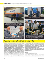
March 2024 - Marine Technology Reporter page: 44NEW TECH OCEANOLOGY INTERNATIONAL 2024 Image courtesy Metron/Cellula Teledyne Marine acquires Valeport: Matt Quartley, MD, Valeport and Ole Søe-Pedersen, VP & Image courtesy Teledyne Marine GM Teledyne Marine announce the deal in London. Pictured (L-R): Cellula Robotics, President, Eric Jackson, Metron
-
 )
March 2024 - Marine Technology Reporter page: 11
)
March 2024 - Marine Technology Reporter page: 11assist in identifying mines and act as a neutralization device. About the Author Bottom mines pose even greater chal- David R. Strachan is a defense analyst and founder of lenges. Unlike contact mines, bottom Strikepod Systems, a research and strategic advisory mines utilize a range of sensors to
-
 )
March 2024 - Marine Technology Reporter page: 9
)
March 2024 - Marine Technology Reporter page: 9from marinas along the western coast. The exact number of lizing laser detection systems can detect mines just below the mines, as well as their locations, remains largely a mystery, surface, even those hiding in murky water. The Airborne Laser although reports suggest that over three hundred have been
-
 )
February 2024 - Maritime Reporter and Engineering News page: 44
)
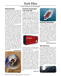
February 2024 - Maritime Reporter and Engineering News page: 44Tech Files Latest Products & Technologies MarineShaft Yanmar Hydrogen MarineShaft specializes in urgent re- Fuel Cell AIP pair/replacement of damaged rudder and Yanmar Power Technology Co., Ltd. propeller equipment along with many (Yanmar PT), a subsidiary of Yanmar on-site repair services. MarineShaft
-
 )
January 2024 - Marine Technology Reporter page: 44
)
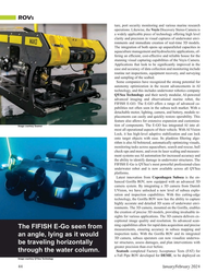
January 2024 - Marine Technology Reporter page: 44ROVS ture, port security monitoring and various marine research operations. Likewise, the Voyis Discovery Stereo Camera is a widely applicable piece of technology offering high level clarity and precision in visual captures of underwater envi- ronments and immediate creation of real-time 3D models.
-
 )
January 2024 - Maritime Reporter and Engineering News page: 4th Cover
)
January 2024 - Maritime Reporter and Engineering News page: 4th CoverENGINEERED COOLING SOLUTIONS OVER 70 YEARS COOLING THE MARINE INDUSTRY R.W. Fernstrum is committed to providing long-lasting, quality marine heat exchangers. Our sales and engineering team will work with you to custom design a solution that meets the needs of your vessel and operating conditions
-
 )
January 2024 - Maritime Reporter and Engineering News page: 38
)
January 2024 - Maritime Reporter and Engineering News page: 38TECH FEATURE ALMACO: Enhanced Sustain hen it comes to sustainability in the maritime tors such as manufacturing footprint and recyclability. Even industry, there are many avenues beyond pow- weight is considered as heavier materials in items such as er and propulsion that vessel owned can ex- beds and
-
![MT Nov-23#24 SEAFLOOR MAPPING & DEEP TREKKER ROVS [SPONSORED]
ENHANCING](https://images.marinelink.com/images/magazines/w200h250c/MarineTechnology-202311-page26.png) )
November 2023 - Marine Technology Reporter page: 24
)
November 2023 - Marine Technology Reporter page: 24SEAFLOOR MAPPING & DEEP TREKKER ROVS [SPONSORED] ENHANCING SEAFLOOR MAPPING AND 3D MODELING: Images courtesy Deep Trekker THE ROLE OF ROVS IN PHOTOGRAMMETRY PROJECTS eneath the ocean’s surface, a technological revolu- Empowering Ef? cient Data Collection tion is reshaping sea? oor mapping and 3D model-
-
 )
November 2023 - Maritime Reporter and Engineering News page: 4th Cover
)
November 2023 - Maritime Reporter and Engineering News page: 4th CoverENGINEERED COOLING SOLUTIONS Join us at the International Workboat Show Booth 2529 OVER 70 YEARS COOLING THE MARINE INDUSTRY R.W. Fernstrum is committed to providing long-lasting, quality marine heat exchangers. Our sales and engineering team will work with you to custom design a solution
-
 )
November 2023 - Maritime Reporter and Engineering News page: 24
)
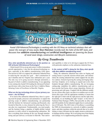
November 2023 - Maritime Reporter and Engineering News page: 24CTO IN FOCUS: DON HAIRSTON, AUSTAL USA ADVANCED TECHNOLOGIES Image courtesy U.S. Navy Additive Manufacturing to Support ‘One plus Two’ Austal USA Advanced Technologies is working with the US Navy on technical solutions that will power the next-gen of navy assets. Don Hairston recently took the helm of the
-
 )
September 2023 - Marine Technology Reporter page: 76
)
September 2023 - Marine Technology Reporter page: 76lighting enable real-time system control and component of this system comprises two feedback from the heart of every subsys- ViperFish torch lights with lasers and a tem. Its robotic systems range from the low power-draw. top-rated and highly-portable Falcon, to its newest deep-rated work system SEAFLOOR
-
 )
September 2023 - Marine Technology Reporter page: 60
)
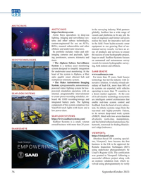
September 2023 - Marine Technology Reporter page: 60MTR Cool New Tech 100 The AUV V u u up p pr rig g g g g gh ht t iiiiiin n n n n n FrameworkRobotics the wate er r r c co o o o o o ol lu um mn n n n n n n n n n w with man n nip pu ul l l l l l lato or r r r r r r r rs s exte e en nd de ed d d d d d d. Courtesy Framework Robotics © DFKI, Thomas Frank of
-
 )
September 2023 - Marine Technology Reporter page: 57
)
September 2023 - Marine Technology Reporter page: 57heat transfer material behind the PCB letters are bare aluminum. components, and do lots of testing pre- to carry the heat away from the LEDs deployment. Cree LEDs produce more (google “CREE LED Luminaire Design Many parts can be purchased by an light per watt, so less heat, and their Guide”). LEDs
-
 )
September 2023 - Marine Technology Reporter page: 49
)
September 2023 - Marine Technology Reporter page: 49UTEC www.acteon.com UTEC, a Geo-services brand in Acteon’s Data and Ro- botics Division, provides a wide range of global survey, positioning and data management services. Surveys performed by UTEC are designed and de- ployed to use less equipment and optimize personnel and vessel usage to reduce the
-
 )
August 2023 - Maritime Reporter and Engineering News page: 4th Cover
)
August 2023 - Maritime Reporter and Engineering News page: 4th CoverWe take the heat, so you don’t have to. Cool. Because you need it. So no matter where you operate, hot days and heavy loads will never slow you down. GRIDCOOLER® Keel Cooler • One Piece Head Design maintains greater structural integrity. • Higher Silver Content Braze Joints resist fatigue and maintain
-
 )
August 2023 - Marine News page: 42
)
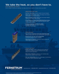
August 2023 - Marine News page: 42maintain door hinges and same amount of cleanup,” Galiardi said. “When we treat locks as well as remove saltwater stains from metal sur- a surface with lasers, any fumes or dislodged particulate faces. In addition, the technology is used for selective de- is extracted into a HEPA ? lter and the job is done
-
 )
August 2023 - Marine News page: 41
)
August 2023 - Marine News page: 41al laser systems are increasingly being used at shipyards, million U.S. workers are at risk of developing silicosis shipbuilding berths and even aboard ships. Technicians and that more than 100,000 of these workers are em- can use mobile handheld units, or if needed the systems ployed as sandblasters.
-
 )
August 2023 - Marine News page: 40
)
August 2023 - Marine News page: 40Tech File Shipyard Tools Clean Technology Lasers: A New Tool to Remove Corrosion and Scale Laser systems quickly remove corrosion and scale from metal surfaces with less preparation and mess than traditional techniques. By Del Williams In the maritime industry, corrosion and scale (where but also
-
 )
August 2023 - Marine News page: 2
)
August 2023 - Marine News page: 2Marine News August 2023 • Volume 34 Number 8 Contents Features 22 An American Success Story 22 David Clark Company has grown from humble beginnings to become a leading designer and manufacturer of crew communication solutions. 28 Need A Lift? U.S. shipyards are adding serious lifting power
-
 )
July 2023 - Marine Technology Reporter page: 33
)
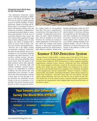
July 2023 - Marine Technology Reporter page: 33Clearing the beach with the Bayo- net 250. Photo Bayonet The autonomous underwater vehicle (AUV) Cuttle? sh, developed at DFKI, serves as the robotic test platform. The AUV has two deep-sea capable gripping systems for ? exible handling of objects underwater. Thanks to its design and AI- based control
-
 )
July 2023 - Marine Technology Reporter page: 16
)
July 2023 - Marine Technology Reporter page: 16LANDER LAB #8 TITANIUM AND OCEAN LANDERS als, occasionally designers are faced with that challenge. It gall, and a higher melting temperature coupled with a sensitiv- is important to recall that corrosion requires both an electron ity to welding contamination. Welding requires shielding from path and an
-
 )
May 2023 - Marine Technology Reporter page: 21
)
May 2023 - Marine Technology Reporter page: 21has been very success- “They’re all about visual imaging sensors, so using cameras and ful,” said Partridge. “Despite the name, ‘Sonardyne’ didn’t re- lasers to provide imaging systems, predominantly for ROVs ally get into imaging sonar. We had a couple of attempts, but and AUVs; they’re like the eyes
-
 )
May 2023 - Maritime Reporter and Engineering News page: 4th Cover
)
May 2023 - Maritime Reporter and Engineering News page: 4th CoverENGINEERED COOLING SOLUTIONS Join us at Inland Marine Expo Booth 515 OVER 70 YEARS COOLING THE MARINE INDUSTRY R.W. Fernstrum is committed to providing long-lasting, quality marine heat exchangers. Our sales and engineering team will work with you to custom design a solution that meets the
-
 )
May 2023 - Maritime Reporter and Engineering News page: 12
)
May 2023 - Maritime Reporter and Engineering News page: 12for structing or updating a map of an unknown environment using corrosion and for gathering hull thickness measurements so technology, such as LIDAR and lasers, while at the same time that a drone or robotic crawler can transmit it to a surveyor keeping track of your location within it. Typically in ? ight