Screw Technology
-
- Innovation in the Engine Space Maritime Reporter, Mar 2002 #27
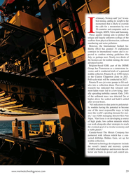
Turn of the century photographs of dirty, hot, cramped machine spaces filled with boilers, engines, gratings and bulkheads begin to tell the story of the state of steam power just after the birth of the propeller. Oil squirt cans, dancing connecting rods, and sweating coal passers and firemen characterized the engine rooms of the late 1800s when paddle wheels were gradually being replaced with the screw.
Pioneers of screw propulsion experimented with an assortment of propeller designs before commercial application of the concept began. The first screw-driven vessel in the U.S. Navy was the Princeton, built in 1843 by John Erickson. Even though the prop had many advantages over the paddle wheel, the fact that during the 1840s and 50s most ships were still made of wood posed significant challenges in terms of power, thrust, and managing the final drive to the propeller shaft.
In terms of engine design and construction, screw technology of the 1850s was much the same as paddle propulsion. Engineers tried a number of existing prime movers including beam, oscillating, and horizontal engines before finally deciding that the vertical direct-acting engine was the best solution.
One of the first installations of a beam engine turned sideways was by shipbuilder Todd & Mac- Gregor who laid down a 1,600-ton iron steamer in 1849. The ship's overhead beam engine had two 66 in. bore by 5 ft. stroke cylinders, each connected to its own beam by means of a connecting rod.
By 1862, the two-cylinder geared oscillating engine was adopted for the Cunard screw steamer China. The cylinders were 80 in. diameter and the stroke 5 ft. 6in. The gear wheels, more widely used than chain drives, contained four rows of wooden teeth, these being less noisy, easier to cut and less of a problem to lubricate than metal teeth.
Horizontal engines were the first truly successful plants for screw-driven vessels. Initially, readily available horizontal engines used for naval steamers were fitted into merchant ships. However the limited width of many merchant ships presented problems with fitting direct-drive horizontal engines.
The solution, according to many builders, was a vertical arrangement. By the mid-1800s, the vertical inverted direct-acting condensing engine became the main engine used on nearly all screwdriven vessels. Cylinders of an inverted engine were mounted on supports bolted to the bedplate, the piston rod of each cylinder passing through its lower cylinder cover and connecting with a crosshead running in guides attached to the cylinder supports. When owners realized that the inverted cylinder engine saved on engine-room floor space, allowing for more cargo, cabins or coal, inverted cylinders arranged vertically above the crankshaft became the norm for screw propul- Compound and Triple Expansion Engines Until this point all steam expansion took place in one cylinder. But with ongoing improvements in compound engines, the days of the simple expansion engine were numbered. By the 1870s compound engines were considered reliable, and the fuel saving advantages of compound expansion were clear. The first of these engines operated at about 60 psi while later compounds would use pressures of 80 to 100 psi. During the early years.
crankshaft strength limited engine power. Not until the introduction of higher quality steel were high output powers possible.
Use of the compound was followed by the triple expansion steam engine, considered reliable by the 1880s. In these engines, which needed a minimum of 120 psi to operate, the steam was exhausted from the high-pressure cylinder to the intermediate cylinder, then to a low-pressure cylinder. A triple expansion engine could operate at around 200 psi with a condenser vacuum of 26 inches of mercury.
The cranks were placed at 120° to give more uniform torque to the shaft. To operate with a higher pressure and offer smoother power, quadruple expansion engines were built as well. However, triple expansion technology dominated until the advent of the steam turbine.
Steam Turbine Invented in the 18th century, the rotary engine was not practical until 1884 when Sir Charles Parsons invented a turbine to operate an electrical generator.
The first turbine-powered vessel was the HMS Turbinia in 1897. This direct-drive engine operated at a relatively slow speed. The main problem with turbines was their high rotation speed — which required use of a reduction gear — and the fact that they were not reversible.
Yet, because of their favorable size-to-power ratio, steam turbines had been adopted for use in many large express passenger liners by the early 1900s. Canadian Pacific's 21,517-gross ton trans-Pacific liner Empress of Canada, which entered service in 1922, typified the period. Her propulsion plant consisted of two sets of Brown-Curtis turbines employing double reduction gearing, each set consisting of four separate turbines in series. During the war the turbine reigned supreme, driving First World War ships from large battleships to destroyers.
During the 1930s, manufacturers were preparing for war production. The main industrial wartime strategies were achieving standardization and developing increased manufacturing capacity and efficiency. Technology temporarily regressed in favor of producibility.
Because of an acute shortage of turbine, gear, and large diesel engine manufacturing capability, the approximately 3,000 ships built during WWII were powered with triple-expansion reciprocating steam engines. The 2,700 Liberty ships supplied by the Allies served the war effort in an exemplary fashion. Despite a significantly behind-the-times fuel rate of about 1.2 lb/ihp-hr, the ships' plants were capable of being operated by relatively inexperienced personnel.
To encourage o u r - ~ age exploitation of better fuel rates and alleviate the anticipated shortage of steam turbines and gears, a few experimental diesel installations took place just before and after the start of WWII. The direct-drive, British-patented, opposed-piston Doxford diesel engines were built in 3-, 4-, and 5-cylinder versions with 6,000 and 7,500 bhp continuous ratings.
These became the popular, American-made, large diesel engines, built by the Sun Shipbuilding and Drydock Company of Pennsylvania.
Postwar Progress After WWII, the unending quest for reduced weight and machinery space continued. By the late 1940s most steam merchant ships were turbine powered.
Striving for heat and space efficiency inevitably led to pressure-fired boilers, or supercharged steam generators.
In such boilers air from a turbine-driven compressor, powered by furnace exhaust gas was fed to the furnace at about 65 psi/490°F.
In the early 1960s U.S. operators of ocean-going vessels began to move toward increased speed and cargo system improvements. Grace lines' four Santa Magdalena- class (with a 20.5 knot speed) became the modern cargo carriers of the day. Both plants, which were of about 18,000 shp maximum, had two oil-fired Dtype water tube boilers supplying 600 lb steam to a single set of cross compound steam turbines driving double reduction gears and a single propeller. This design represented a conservative standard for U.S. power plants for the next decade.Relief from wartime restrictions led to more experimentation. More than 1,000 nearly new Liberty ships were targeted as working test beds and outfitted with a steam turbine, a free piston gas turbine, a regenerative gas turbine, or a diesel engine. The most notable of the Liberties was the John Sergeant converted in 1956 with a 6,000 shp opencycle regenerative gas turbine, double-reduction gears, and a controllable, reversible-pitch propeller.
Gas Turbine When the U.S. Navy made the transition to light dis- tillate fuel in the late 1960s and early 70s, the shift paved the way for a transition to more diesel- and gas turbine-powered combatants. By effectively equalizing the cost of the basic propulsion fuel, the cost advantage of the steam plant was lost and a logistical advantage for gas turbine power was born.
The gas turbine was touted as a compact, fuel-efficient plant that offered high power per unit weight.
While the concept predates the 20th century, it was not until after WWII that gas turbines began to find wide acceptance and application in power generation and propulsion. The first U.S. gas turbine-propelled merchant ship was the above-mentioned John Sergeant. Its low compression ratio, heavy-duty, industrial-type gas turbine's fuel consumption rate was a respectable 0.52 lb/shp-hr. By 1965 the Navy had installed many gas turbines for electric and auxiliary power, but only 78 for propulsion. One major step was the Navy's combined- diesel-or-gas propulsion plant for patrol motor gunboats, using diesel engines for cruising and a GE LM1500 gas turbine of 14,000 hp for high-speed operations.
Diesel Engine Drives Throughout the 1920s and 1930s the diesel engine found increasing favor with many ship owners because it was more economic to operate. Scandinavian ship owners turned almost exclusively to diesel. Only in terms of the large express liner could steam be classed as more economic than diesel in the late 1930s.
In the years preceding WWII, most diesels installed in the U.S. were direct drive reversing engines. Rapid expansion of demand for engines in the 50s and 60s led to a wide range of engines for propulsion varied from about 100 to about 5,000 bhp. Single reduction gear sets fitted with controllable reversing propellers or reversing reduction gears were available in a variety of sizes and the installation and capital costs of this arrangement were considerably lower than those of a steam plant.
Postwar diesel engine development proceeded in two almost diametrically opposed directions. For naval applications, engines were small, high-speed, and light-weight. Yet in merchant ships the trend was toward large, slow-speed engines of high power and high efficiency that burned costly fuels and maintained lower rpm to match lower propeller speeds. Diesel propulsion became more and more dominant in merchant ships even before the oil shortage in the 1970s overshadowed all other considerations in selecting machinery.
Marine Power Plants Today In the late 80s and early 90s engineers began to recognize the attributes of gas turbine power that would make it acceptable for commercial use. To preserve the maximum amount of ship space for generating revenue, owners sought compact and lightweight power solutions. The first main commercial use for gas turbines was in fast ferries. Today, space concerns and environmental interests have led some cruise lines to take another look at gas turbine technology.
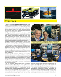
Citing a goal to produce "the most environmentally sensitive cruise ships in the world," Demetrios Kaparis broke new ground in 2000 with his decision to implement gas turbine power — a technology he considers to be the "future of marine power plants" — on Celebrity's Millennium. While fuel cr ' are greater because of the use of distillates, some cruise lines have discovered an economic advantage to gas turbine-based plants, according to Dave Luck, manager of marine applications and ship integration at GE. "Having more cabins in the ship can more than offset the higher fuel cost." said Luck. In addition, pending environmental regulations and increased concern about exhaust emissions in some of the regions cruise ships serve have further influenced the decision to choose gas turbines.
Increasing environmental concern has also garnered new attention to earlier experiments with liquified natural gas (LNG) carriers. By next year, if all goes according to plan.
Statoil will become the first operator on the Norwegian continental shelf to feature LNG powered propulsion on its vessels.
While the construction cost of each vessel increased by $6 million, the company chose LNG technology because it would greatly reduce emissions.
Sources: Steam at Sea, by Dennis Griffiths, Conway Maritime Press, 1997.
Smoke Ash and Steam: Steam Engines on the West Coast of North America, by Robin E. Slieret. Western Isle & Cruise Drive Co. Ltd. 1997.
A Half Century of Maritime Technology 1943-1993, Ed.
by Harry Benford and William A. Fox: Powering Section written by David O'Neil, the Society of Naval Architects and Marine Engineers, 1993.
A freelance journalist for Newsweek, Rolling Stone, and Newsday, among other publications, Jessica DuLong is also assistant chief engineer on retired New York City fire - boat John J. Harvex.
-
 )
March 2024 - Marine Technology Reporter page: 48
)
March 2024 - Marine Technology Reporter page: 48Index page MTR MarApr2024:MTR Layouts 4/4/2024 3:19 PM Page 1 Advertiser Index PageCompany Website Phone# 17 . . . . .Airmar Technology Corporation . . . . . . . . . .www.airmar.com . . . . . . . . . . . . . . . . . . . . . . . . . . . . . . . . .(603) 673-9570 9 . . . . . .Birns, Inc. . . . . . . . . . .
-
 )
March 2024 - Marine Technology Reporter page: 47
)
March 2024 - Marine Technology Reporter page: 47PRODUCT, PROFESSIONAL, VESSELS, MTR BARGES & REAL ESTATE FOR SALE Marketplace INNOVATIVE. UNIQUE. PROVEN. ALLAMERICANMARINE.com ???????????????????????????????????????? 9??????????SiC A????????ArC????????????????S???????C?????????9???Ç????????? ????????????????Ý???????S???y???????????????????K???:???? MAR
-
 )
March 2024 - Marine Technology Reporter page: 45
)
March 2024 - Marine Technology Reporter page: 45ronments. The new agreement will address speci? c techni- cal gaps in the UUV defense and offshore energy markets especially for long duration, multi-payload mission opera- tions where communications are often denied or restricted. As part of the new alliance, Metron’s Resilient Mission Autonomy portfolio
-
 )
March 2024 - Marine Technology Reporter page: 43
)
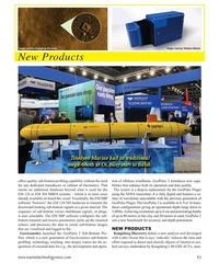
March 2024 - Marine Technology Reporter page: 43Image courtesy Kongsberg Discovery Image courtesy Teledyne Marine New Products Teledyne Marine had its traditional mega-booth at Oi, busy start to ? nish. Image courtesy Greg Trauthwein offers quality sub-bottom pro? ling capability without the need tion of offshore windfarms. GeoPulse 2 introduces new
-
 )
March 2024 - Marine Technology Reporter page: 41
)
March 2024 - Marine Technology Reporter page: 41Image courtesy Outland Technology Image courtesy Exail Image courtesy Submaris and EvoLogics Vehicles The ROV-1500 from Outland Technology represents a leap forward in underwater robotics, a compact remotely operated vehicle (ROV) weighing in at less than 40 lbs (19kg) the ROV- 1500 is easy to transport
-
 )
March 2024 - Marine Technology Reporter page: 40
)
March 2024 - Marine Technology Reporter page: 40NEW TECH OCEANOLOGY INTERNATIONAL 2024 All photos courtesy MTR unless otherwise noted NEW TECH, PARTNERSHIPS LAUNCH IN LONDON With Oceanology International now one month in the rear-view mirror, MTR takes a look at some of the interesting technologies launched before, during and after the London event.
-
 )
March 2024 - Marine Technology Reporter page: 37
)
March 2024 - Marine Technology Reporter page: 37miscible barrier ? uid heavier than seawater (sg=1.026) and lighter than the battery electrolyte (sg=1.265). The original cell vent cap was screwed into the top of the riser pipe to vent the gases associated with charging. Wires were soldered to the lead (Pb) posts. The lead-acid battery was additionall
-
 )
March 2024 - Marine Technology Reporter page: 33
)
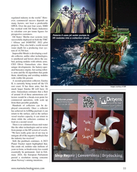
March 2024 - Marine Technology Reporter page: 33regulated industry in the world.” How- ever, commercial success depends on many factors, not least a predictable OPEX. Over the past four years, SMD has worked with Oil States Industries to calculate cost per tonne ? gures for prospective customers. Patania II uses jet water pumps to Oil States’
-
 )
March 2024 - Marine Technology Reporter page: 32
)
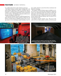
March 2024 - Marine Technology Reporter page: 32FEATURE SEABED MINING by a sea? oor plume from its pilot collection system test. pact, nodule collection system that utilizes mechanical and The Metals Company recently signed a binding MoU with hydraulic technology. Paci? c Metals Corporation of Japan for a feasibility study on The company’s SMD
-
 )
March 2024 - Marine Technology Reporter page: 30
)
March 2024 - Marine Technology Reporter page: 30FEATURE SEABED MINING bilical. It has passive heave compensation which nulli? es the necott. “The focus since then has been on scaling while en- wave, current and vessel motions that in? uence loads in the suring the lightest environmental impact,” says The Metals power umbilical. The LARS can
-
 )
March 2024 - Marine Technology Reporter page: 29
)
March 2024 - Marine Technology Reporter page: 29n January, Norway said “yes” to sea- bed mining, adding its weight to the momentum that is likely to override the calls for a moratorium by over 20 countries and companies such as I Google, BMW, Volvo and Samsung. Those against mining aim to protect the unique and largely unknown ecology of the sea?
-
 )
March 2024 - Marine Technology Reporter page: 27
)
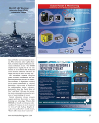
March 2024 - Marine Technology Reporter page: 27SEA-KIT USV Maxlimer returning from HT-HH caldera in Tonga. © SEA-KIT International data and further assess ecosystem recov- ery. What is known, noted Caplan-Auer- bach, is that the impact of submarine vol- canoes on humans is rare. “The HT-HH eruption was a tragedy, but it was very unusual. It let us
-
 )
March 2024 - Marine Technology Reporter page: 26
)
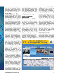
March 2024 - Marine Technology Reporter page: 26FEATURE OCEANOGRAPHIC INSTRUMENTATION & SENSORS Kevin Mackay, TESMaP voyage leader and Center head of the South and West Paci? c Regional Centre of Seabed 2030. Kevin in the seismic lab at Greta Point looking at the Hunga Tonga-Hunga Ha’apai volcano 3D map completed with data from the TESMaP voyage
-
 )
March 2024 - Marine Technology Reporter page: 25
)
March 2024 - Marine Technology Reporter page: 25Auerbach explained that ideally, “one ? ed layers of geothermal activity,” noted changes over an area of 8,000 km2. They would have both instruments: seismom- Skett, “and the change in salinity and dis- found up to seven km3 of displaced ma- eters to detect and locate subsurface ac- solved particles for
-
 )
March 2024 - Marine Technology Reporter page: 23
)
March 2024 - Marine Technology Reporter page: 23elatively inactive since 2014, the Hunga Tonga–Hunga Ha‘apai (HT-HH) submarine volcano began erupting on December 20, 2021, reaching peak intensity on January 15, 2022. This triggered tsunamis throughout the Pa- R ci? c, destroyed lives and infrastructure, and generated the largest explosion recorded
-
 )
March 2024 - Marine Technology Reporter page: 20
)
March 2024 - Marine Technology Reporter page: 202024 Editorial Calendar January/Februay 2024 February 2024 March/April 2024 Ad close Jan.31 Ad close March 21 Ad close Feb. 4 Underwater Vehicle Annual Offshore Energy Digital Edition ?2?VKRUH:LQG$)ORDWLQJ)XWXUH ?2FHDQRJUDSKLF?QVWUXPHQWDWLRQ 6HQVRUV ?6XEVHD'HIHQVH ?6XEVHD'HIHQVH7KH+XQWIRU ?0DQLS
-
 )
March 2024 - Marine Technology Reporter page: 19
)
March 2024 - Marine Technology Reporter page: 19About the Author vey with the pipe tracker is not required, resulting in signi? - Svenn Magen Wigen is a Cathodic Protection and corrosion control cant cost savings, mainly related to vessel charter. expert having worked across The major advantage of using FiGS on any type of subsea engineering, design
-
 )
March 2024 - Marine Technology Reporter page: 18
)
March 2024 - Marine Technology Reporter page: 18TECH FEATURE IMR There are also weaknesses in terms of accuracy because of FiGS Operations and Bene? ts signal noise and the ability to detect small ? eld gradients. In Conventional approaches to evaluating cathodic protection this process there is a risk that possible issues like coating (CP)
-
 )
March 2024 - Marine Technology Reporter page: 17
)
March 2024 - Marine Technology Reporter page: 17• Integrity assessment, and otherwise covered, e.g., by rock dump. As for depletion of • Mitigation, intervention and repair. sacri? cial anodes, this can be dif? cult or even impossible to Selecting the best method for collecting the data these work- estimate due to poor visibility, the presence of
-
 )
March 2024 - Marine Technology Reporter page: 16
)
March 2024 - Marine Technology Reporter page: 16TECH FEATURE IMR Image courtesy FORCE Technology OPTIMIZING CATHODIC PROTECTION SURVEY USING NON-CONTACT SENSORS By Svenn Magen Wigen, FORCE Technology he principle behind sacri? cial anodes, which are water structures, reducing the need for frequent repairs and used to safeguard underwater pipelines
-
 )
March 2024 - Marine Technology Reporter page: 15
)
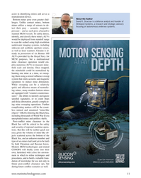
March 2024 - Marine Technology Reporter page: 15sensor options for longer mission periods. About the Author For glider users working in ? sheries and conservation, Shea Quinn is the Product Line Manager the Sentinel can run several high-energy passive and active of the Slocum Glider at Teledyne Webb acoustic sensors, on-board processing, and imaging
-
 )
March 2024 - Marine Technology Reporter page: 13
)
March 2024 - Marine Technology Reporter page: 13nyone familiar with glider hardware options integrated for a broad Glider answers that need,” said Shea autonomous underwater ve- range of missions. Quinn, Slocum Glider Product Line hicles (AUVs) is certainly “As the use of Slocum Gliders grew, Manager at TWR. A familiar with the popular- so did
-
 )
March 2024 - Marine Technology Reporter page: 11
)
March 2024 - Marine Technology Reporter page: 11assist in identifying mines and act as a neutralization device. About the Author Bottom mines pose even greater chal- David R. Strachan is a defense analyst and founder of lenges. Unlike contact mines, bottom Strikepod Systems, a research and strategic advisory mines utilize a range of sensors to
-
 )
March 2024 - Marine Technology Reporter page: 9
)
March 2024 - Marine Technology Reporter page: 9from marinas along the western coast. The exact number of lizing laser detection systems can detect mines just below the mines, as well as their locations, remains largely a mystery, surface, even those hiding in murky water. The Airborne Laser although reports suggest that over three hundred have been