Page 56: of Marine News Magazine (November 2020)
Workboat Annual
Read this page in Pdf, Flash or Html5 edition of November 2020 Marine News Magazine
ech file
T
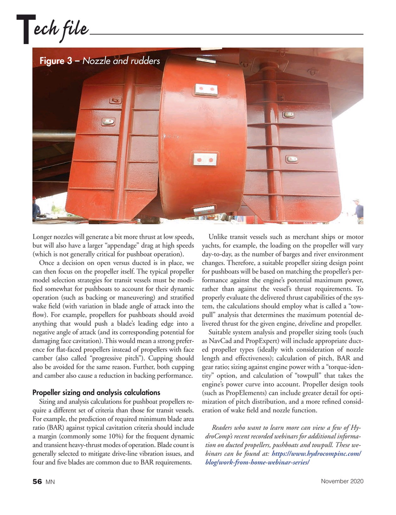
Figure 3 – Nozzle and rudders
Longer nozzles will generate a bit more thrust at low speeds, Unlike transit vessels such as merchant ships or motor but will also have a larger “appendage” drag at high speeds yachts, for example, the loading on the propeller will vary (which is not generally critical for pushboat operation). day-to-day, as the number of barges and river environment
Once a decision on open versus ducted is in place, we changes. Therefore, a suitable propeller sizing design point can then focus on the propeller itself. The typical propeller for pushboats will be based on matching the propeller’s per- model selection strategies for transit vessels must be modi- formance against the engine’s potential maximum power, ? ed somewhat for pushboats to account for their dynamic rather than against the vessel’s thrust requirements. To operation (such as backing or maneuvering) and strati? ed properly evaluate the delivered thrust capabilities of the sys- wake ? eld (with variation in blade angle of attack into the tem, the calculations should employ what is called a “tow- ? ow). For example, propellers for pushboats should avoid pull” analysis that determines the maximum potential de- anything that would push a blade’s leading edge into a livered thrust for the given engine, driveline and propeller.
negative angle of attack (and its corresponding potential for Suitable system analysis and propeller sizing tools (such damaging face cavitation). This would mean a strong prefer- as NavCad and PropExpert) will include appropriate duct- ence for ? at-faced propellers instead of propellers with face ed propeller types (ideally with consideration of nozzle camber (also called “progressive pitch”). Cupping should length and effectiveness); calculation of pitch, BAR and also be avoided for the same reason. Further, both cupping gear ratio; sizing against engine power with a “torque-iden- and camber also cause a reduction in backing performance. tity” option, and calculation of “towpull” that takes the engine’s power curve into account. Propeller design tools
Propeller sizing and analysis calculations (such as PropElements) can include greater detail for opti-
Sizing and analysis calculations for pushboat propellers re- mization of pitch distribution, and a more re? ned consid- quire a different set of criteria than those for transit vessels. eration of wake ? eld and nozzle function.
For example, the prediction of required minimum blade area ratio (BAR) against typical cavitation criteria should include Readers who want to learn more can view a few of Hy- a margin (commonly some 10%) for the frequent dynamic droComp’s recent recorded webinars for additional informa- and transient heavy-thrust modes of operation. Blade count is tion on ducted propellers, pushboats and towpull. These we- generally selected to mitigate drive-line vibration issues, and binars can be found at: https://www.hydrocompinc.com/ four and ? ve blades are common due to BAR requirements. blog/work-from-home-webinar-series/
November 2020
MN 56

 55
55

 57
57
