
Page 63: of Offshore Engineer Magazine (Nov/Dec 2013)
Read this page in Pdf, Flash or Html5 edition of Nov/Dec 2013 Offshore Engineer Magazine
 62
62
 64
64
the amount of testing time on critical path. Once mo- bilization and testing is complete, the vessel runs the multiplex (MUX) controlled intervention riser system to depth, utilizing a dual-string riser. The intervention riser system is unique and is comprised of a lower riser package (LRP) with a 7 3/8” production through bore.
The LRP also provides cut and seal fail-safe barriers on both the annulus and production sides.
The IRS system is also equipped with a emergency disconnect package (EDP) to quickly detach and seal in the event of an emergency or station keeping incident.
The EDP itself is equipped with a valve to ensure riser fuids are retained within the pressurized riser should the emergency disconnect sequence be required. The
IRS system is a lighter package than a traditional blow- out preventer (BOP), minimizing stress on the support- ing well tree during latching.
Managing down lines, MUX cables, and a separate annulus line while operating an IRS requires proper set-up and an experienced crew. The riser also should be pressure-tested periodically to confrm riser integrity while running.
ACCESSING THE WELL
WITH THE IRS PACKAGE
Once the IRS package is ran to depth in an identifed safe zone, riser space out is confrmed by moving the
IRS package over the well. The surface system is then rigged up with fow head, coil tubing lift frame and coil tubing BOPs once it returns to the safe zone.
The system is then landed and latched up on the well utilizing passive and active heave compensation.
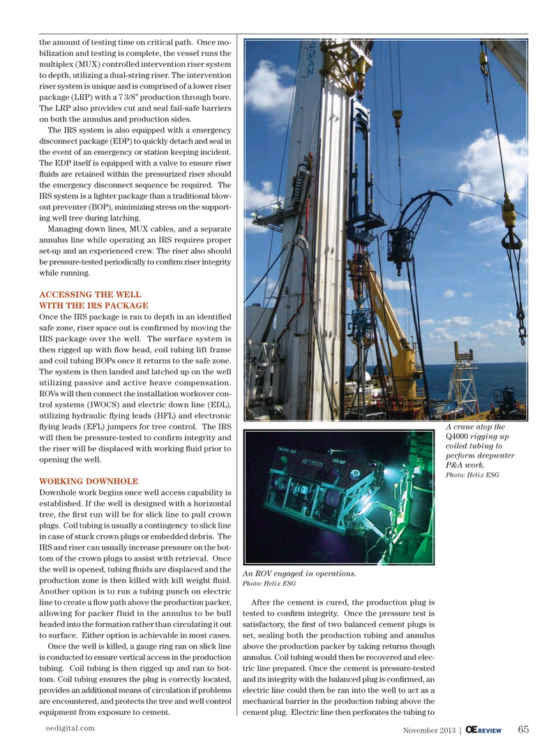
ROVs will then connect the installation workover con- trol systems (IWOCS) and electric down line (EDL), utilizing hydraulic fying leads (HFL) and electronic fying leads (EFL) jumpers for tree control. The IRS A crane atop the
Q4000 rigging up will then be pressure-tested to confrm integrity and coiled tubing to the riser will be displaced with working fuid prior to perform deepwater opening the well.
P&A work.
Photo: Helix ESG
WORKING DOWNHOLE
Downhole work begins once well access capability is established. If the well is designed with a horizontal tree, the frst run will be for slick line to pull crown plugs. Coil tubing is usually a contingency to slick line in case of stuck crown plugs or embedded debris. The
IRS and riser can usually increase pressure on the bot- tom of the crown plugs to assist with retrieval. Once the well is opened, tubing fuids are displaced and the
An ROV engaged in operations. production zone is then killed with kill weight fuid.
Photo: Helix ESG
Another option is to run a tubing punch on electric line to create a fow path above the production packer, After the cement is cured, the production plug is allowing for packer fluid in the annulus to be bull tested to confrm integrity. Once the pressure test is headed into the formation rather than circulating it out satisfactory, the frst of two balanced cement plugs is to surface. Either option is achievable in most cases. set, sealing both the production tubing and annulus
Once the well is killed, a gauge ring ran on slick line above the production packer by taking returns though is conducted to ensure vertical access in the production annulus. Coil tubing would then be recovered and elec- tubing. Coil tubing is then rigged up and ran to bot- tric line prepared. Once the cement is pressure-tested tom. Coil tubing ensures the plug is correctly located, and its integrity with the balanced plug is confrmed, an provides an additional means of circulation if problems electric line could then be ran into the well to act as a are encountered, and protects the tree and well control mechanical barrier in the production tubing above the equipment from exposure to cement. cement plug. Electric line then perforates the tubing to oedigital.com 65
November 2013 | OE REVIEW 064_OE1113_Dif_Helix.indd 65 10/28/13 2:12 AM