
Page 26: of Offshore Engineer Magazine (Dec/Jan 2013)
Read this page in Pdf, Flash or Html5 edition of Dec/Jan 2013 Offshore Engineer Magazine
 25
25
 27
27
Applying real-time magnetic declination in arctic marine
Geology & Geophysics seismic acquisition
By Curt Schneider, improvement of real-time declinations over modeled declinations for marine
ION Geophysical seismic streamer positioning in the and Noel Zinn,
Arctic.
Hydrometronics
Characterizing Arctic geomagnetism
The Earth’s magnetic feld is a compos- arine seismic surveying in ite of several magnetic felds generated the Arctic presents many by a variety of sources. These felds are
M challenges. Conducting superimposed on each other and through streamer surveys in the presence of inductive processes interact with each high ice concentrations eliminates the other (www.ngdc.noaa.gov). The most ability to safely tow a conventional GPS important of these geomagnetic felds are: tail buoy. When conducting 2D surveys The main magnetic feld F (s,t) core
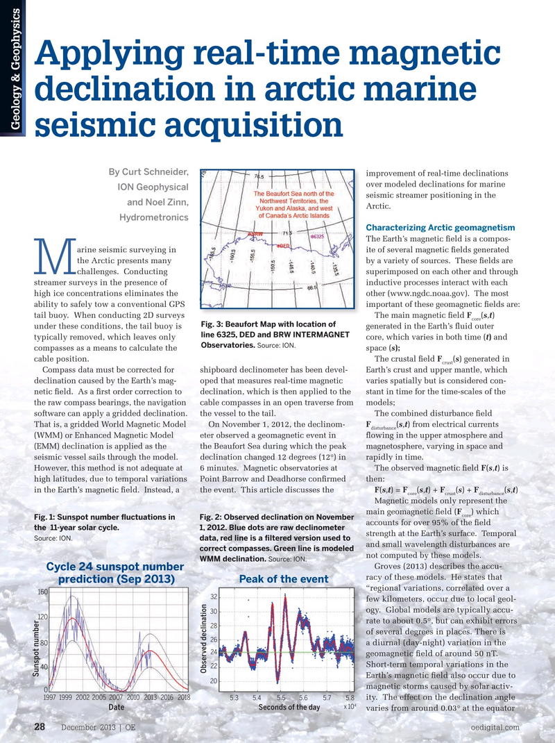
Fig. 3: Beaufort Map with location of under these conditions, the tail buoy is generated in the Earth’s fuid outer line 6325, DED and BRW INTERMAGNET typically removed, which leaves only core, which varies in both time (t) and
Observatories. Source: ION.
compasses as a means to calculate the space (s); cable position. The crustal feld F (s) generated in crust
Compass data must be corrected for shipboard declinometer has been devel- Earth’s crust and upper mantle, which declination caused by the Earth’s mag- oped that measures real-time magnetic varies spatially but is considered con- netic feld. As a frst order correction to declination, which is then applied to the stant in time for the time-scales of the the raw compass bearings, the navigation cable compasses in an open traverse from models; software can apply a gridded declination. the vessel to the tail. The combined disturbance feld
That is, a gridded World Magnetic Model On November 1, 2012, the declinom- F (s,t) from electrical currents disturbance (WMM) or Enhanced Magnetic Model eter observed a geomagnetic event in fowing in the upper atmosphere and (EMM) declination is applied as the the Beaufort Sea during which the peak magnetosphere, varying in space and seismic vessel sails through the model. declination changed 12 degrees (12°) in rapidly in time.
However, this method is not adequate at 6 minutes. Magnetic observatories at The observed magnetic feld F(s,t) is high latitudes, due to temporal variations Point Barrow and Deadhorse confrmed then: in the Earth’s magnetic feld. Instead, a the event. This article discusses the F(s,t) = F (s,t) + F (s) + F (s,t) core crust disturbance
Magnetic models only represent the main geomagnetic feld (F ) which core
Fig. 1: Sunspot number fuctuations in Fig. 2: Observed declination on November accounts for over 95% of the feld the 11-year solar cycle. 1, 2012. Blue dots are raw declinometer strength at the Earth’s surface. Temporal
Source: ION.
data, red line is a fltered version used to and small wavelength disturbances are correct compasses. Green line is modeled not computed by these models.
WMM declination. Source: ION.
Groves (2013) describes the accu-
Cycle 24 sunspot number racy of these models. He states that
Peak of the event prediction (Sep 2013) “regional variations, correlated over a 160 32 few kilometers, occur due to local geol- ogy. Global models are typically accu- 30 120 rate to about 0.5°, but can exhibit errors 28 of several degrees in places. There is 26 a diurnal (day-night) variation in the 80 24 geomagnetic feld of around 50 nT.
Short-term temporal variations in the 22 40
Observed declination
Sunspot number
Earth’s magnetic feld also occur due to 20 magnetic storms caused by solar activ- 0 ity. The effect on the declination angle 199719992002200520072010201320162018 5.3 5.4 5.5 5.6 5.7 5.8 4 x 10
Seconds of the day
Date varies from around 0.03° at the equator
December 2013 | OE oedigital.com 28 028_1213_G&G- ION.indd 28 11/22/13 4:19 PM