
Page 66: of Offshore Engineer Magazine (Nov/Dec 2014)
Read this page in Pdf, Flash or Html5 edition of Nov/Dec 2014 Offshore Engineer Magazine
 65
65
 67
67
simulation of ice radial direction, starting from the contact loads on vertical- point. These radial cracks are due to the walled structures. tension at the bottom of the ice plate.
The effect of cir- Increasing the forces applied on the ice
Arctic cumferential cracks will increase the number of radial cracks formation on the and lengthen them until a circumferen- ice load value is so tial crack is formed. In the simulator, small it can be safely fve wedge-shaped beams resting on an neglected. elastic foundation are used to model the
For the purposes cracking.
of this simulator, Ice fragments make up an important the structure, ice part of ice loads and these can be taken fragments and ice into account using a semi-infnite plate
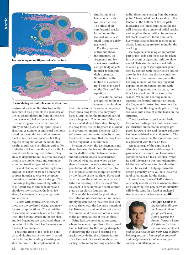
Ice modeling on multiple conical structure.
sheet are considered model. This simulates ice sheet failure as rigid body objects due to a pile up of ice fragments gener- in order to compute ated by contact with the structure falling their dynamics. onto the ice sheet. As the ice continues
Simulation of the to break up, the program computes the motion of a system of bending moment of each ice fragment rigid bodies is based depending on its contact points with on the Newton-Euler other ice fragments, the structure, the equations. intact ice sheet, and if necessary, the
Two external forces seabed. When this bending moment are applied to the ice exceeds the fexural strength criterion,
Ice modeling on multiple conical structure.
fragments to simulate the fragment is broken into two new ice horizontal loads on the structure with their interaction with water: a buoyancy fragments. As the fragments pile up, they accuracy. It also predicts the geometry of force and a drag force. The buoyancy are taken into account in the loads on the the ice accumulation in front of the struc- force is applied on the immersed part of structure.
There have been experimental basin ture, above and below the ice sheet. the ice fragment. The volume of this part tests of ice loadings on a multifaceted con-
Ice moving against a structure can is calculated at each time step. To apply ical structure similar to the designs pro- fail by bending, crushing, splitting and the drag force, the ice fragment is divided posed for Arctic use, and the new software shearing. A number of empirical methods into several volumetric elements. CFD has been validated against these tests. The based on ice model tests allow assess- software computes water velocity around validation shows that the model results are ment of ice load components, but they the structure and from that the drag force in agreement with the basin tests. require extrapolation of the model test on the fragment is determined.
results to full-scale conditions and suffer Friction between the ice fragments and An advantage of the simulator is limitations if ice strength or the ice thick- sheet, between the ice and the structure, allowing users to test a wide range of ness differs from required values. They and in shallow water, between the ice parameters in a short time frame when are also dependent on the structure shape and the seabed, has to be considered. compared to basin tests. Ice sheet veloc- used in the model tests, and cannot be To model what happens when an ice ity and thickness, structural orientation, extended to other types of structure. sheet advances towards a structure, the frictional coeffcients and ice elevation
BV and Cervval are combining knowl- penetration depth of the structure into can all be varied to help optimize the edge of ice behavior from a number of the ice sheet is increased up to a limit set design geometry, or to validate the struc- sources in order to create a complete by the failure of the ice sheet. For a coni- tural calculations for the design.
In conclusion, the IceSTAR software numerical simulator for ice design. The cal structure, the most common cause of accurately models ice loads when the struc- tool brings together several algorithms failure is bending on the ice sheet. The ture is moving, this new software simulator of different scales and behaviors, and ice sheet is considered as a semi-infnite will do the same for a fxed or anchored simulates the structure, the level ice plate on an elastic foundation. structure where the ice is moving. sheet, ice fragments, ice pile up, water This model is useful for predicting and currents. the initiation of cracks formed in the ice,
Philippe Cambos is
It starts with conical structures, as simply by comparing the stress levels in the technical director these are the preferred design geometry the ice sheet with the fexural strength of in charge of oil and for Arctic applications. The simulation ice. However, this alone does not predict gas projects, and of ice behavior can be taken in two steps. the number and the extent of the cracks
Arctic projects for
First, the fexural cracks in the ice sheet or the ultimate failure of the ice sheet.
Bureau Veritas Marine and ice fragments are calculated, then the Using fracture mechanics concepts, & Offshore Division. behavior of individual ice fragments and where the energy input from the external
He is a naval architect the sheet are modeled. load is balanced by the energy dissipated and helped develop the VeriSTAR software
The simulation of ice loads on coni- in deforming the ice and creating the before going on to handle plan approval cal and sloping wall structures is based cracks helps defne the ultimate failure and design review for oil tankers, gas on ice failing in bending. Crushing and of an ice sheet. Observations show that carriers and offshore units. shear failure will be implemented for ice begins to fail by forming cracks in the
November 2014 | OE oedigital.com 68 000_OE1114_Geo4_EPIC1_veritas.indd 68 10/21/14 6:06 PM