
Page 42: of Offshore Engineer Magazine (Apr/May 2015)
Read this page in Pdf, Flash or Html5 edition of Apr/May 2015 Offshore Engineer Magazine
 41
41
 43
43
coef? cients. To arrive at such ? eld spe-
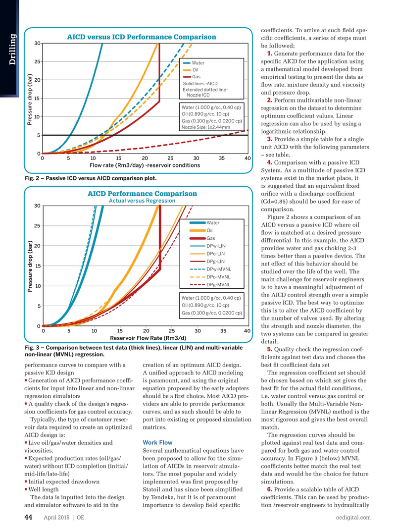
AICD versus ICD Performance Comparison ci? c coef? cients, a series of steps must 30 be followed; 1.
Generate performance data for the speci? c AICD for the application using 25
Water
Drilling a mathematical model developed from
Oil
Gas empirical testing to present the data as 20
Solid lines -AICD ? ow rate, mixture density and viscosity
Extended dotted line - and pressure drop.
Nozzle ICD 15 2.
Perform multivariable non-linear
Water (1.000 g/cc, 0.40 cp) regression on the dataset to determine
Oil (0.890 g/cc, 10 cp) optimum coef? cient values. Linear 10
Gas (0.100 g/cc, 0.0200 cp) regression can also be used by using a
Nozzle Size: 1x2.44mm logarithmic relationship.
5 3.
Provide a simple table for a single unit AICD with the following parameters 0 0510152025303540 – see table. 4. Comparison with a passive ICD
Flow rate (Rm3/day) -reservoir conditions
System. As a multitude of passive ICD systems exist in the market place, it
Fig. 2 – Passive ICD versus AICD comparison plot.
is suggested that an equivalent ? xed ori? ce with a discharge coef? cient
AICD Performance Comparison
Actual versus Regression (Cd=0.85) should be used for ease of 30 comparison.
Figure 2 shows a comparison of an
Water
AICD versus a passive ICD where oil 25
Oil ? ow is matched at a desired pressure
Gas differential. In this example, the AICD
DPw-LIN 20 provides water and gas choking 2-3
DPo-LIN times better than a passive device. The
DPg-LIN net effect of this behavior should be 15
DPw-MVNL studied over the life of the well. The
DPo-MVNL main challenge for reservoir engineers
DPg-MVNL 10 is to have a meaningful adjustment of
Pressure drop (bar) Pressure drop (bar) the AICD control strength over a simple
Water (1.000 g/cc, 0.40 cp) passive ICD. The best way to optimize
Oil (0.890 g/cc, 10 cp) 5 this is to alter the AICD coef? cient by
Gas (0.100 g/cc, 0.0200 cp) the number of valves used. By altering the strength and nozzle diameter, the 0 05 10 15 20 25 30 35 40 two systems can be compared in greater
Reservoir Flow Rate (Rm3/d) detail.
Fig. 3 – Comparison between test data (thick lines), linear (LIN) and multi-variable 5.
Quality check the regression coef- non-linear (MVNL) regression.
? cients against test data and choose the performance curves to compare with a creation of an optimum AICD design. best ? t coef? cient data set passive ICD design A uni? ed approach to AICD modeling The regression coef? cient set should •
Generation of AICD performance coef? - is paramount, and using the original be chosen based on which set gives the cients for input into linear and non-linear equation proposed by the early adopters best ? t for the actual ? eld conditions, regression simulators should be a ? rst choice. Most AICD pro- i.e. water control versus gas control or •
A quality check of the design’s regres- viders are able to provide performance both. Usually the Multi-Variable Non- sion coef? cients for gas control accuracy. curves, and as such should be able to linear Regression (MVNL) method is the
Typically, the type of customer reser- port into existing or proposed simulation most rigorous and gives the best overall voir data required to create an optimized matrices. match.
The regression curves should be
AICD design is:
Live oil/gas/water densities and • Work Flow plotted against real test data and com-
Several mathematical equations have pared for both gas and water control viscosities,
Expected production rates (oil/gas/ • been proposed to allow for the simu- accuracy. In Figure 3 (below) MVNL water) without ICD completion (initial/ lation of AICDs in reservoir simula- coef? cients better match the real test mid-life/late-life) tors. The most popular and widely data and would be the choice for future
Initial expected drawdown • implemented was ? rst proposed by simulations.
Well length Provide a scalable table of AICD • 6.
Statoil and has since been simpli? ed
The data is inputted into the design coef? cients. This can be used by produc- by Tendeka, but it is of paramount and simulator software to aid in the tion /reservoir engineers to hydraulically importance to develop ? eld speci? c
April 2015 | OE oedigital.com 44 042_OE0415_D&C1_Tendeka.indd 44 3/23/15 2:31 PM