
Page 34: of Marine Technology Magazine (Sep/Oct 2014)
Ocean Observation: Gliders, Buoys & Sub-Surface Networks
Read this page in Pdf, Flash or Html5 edition of Sep/Oct 2014 Marine Technology Magazine
 33
33
 35
35
latest technological innovations have lead to fi ber optic links capable of transmitting data at a rate of 1Tb/s.
DWDM operates in the C and L bands (1520 nm to 1620 nm). Optical circulators are available that can span this en- tire spectral range. Optical amplifi ers are also available in this spectral band to increase the reach of a fi ber optic network.
Because of these components cover the same spectral range, we can combine DWDM and optical circulators to construct our network. To connect multiple devices on a single fi ber, we would build two identical OADM networks; one for the dry end and one for the wet end. Each add/drop port would have a circulator to route signals to and from each device’s trans- ceiver module. Each device, along with its dry end controller, would transmit and receive over the network as though it were the only device present. It would be oblivious to the other de- vices operating at different wavelengths.
One advantage of this architecture is that we have simultane- ous communications on our network. Another is that there is no requirement to construct a fi ber ring to complete the net- work; the network is a single string rather than a closed loop.
The network is also easily reconfi gured. In ring architectures, removing a device breaks the ring. With a DWDM network, we simply unplug the device and cap the unused connector.
Adding a device is easily done by adding another OADM to the end of the network. The disadvantages are that the network is more complex to construct and that the various devices can- not communicate directly with one another. Any device to device communication must be done through a server that’s probably aboard the support vessel.
Yet another benefi t of DWDM is the ability to reduce cost by
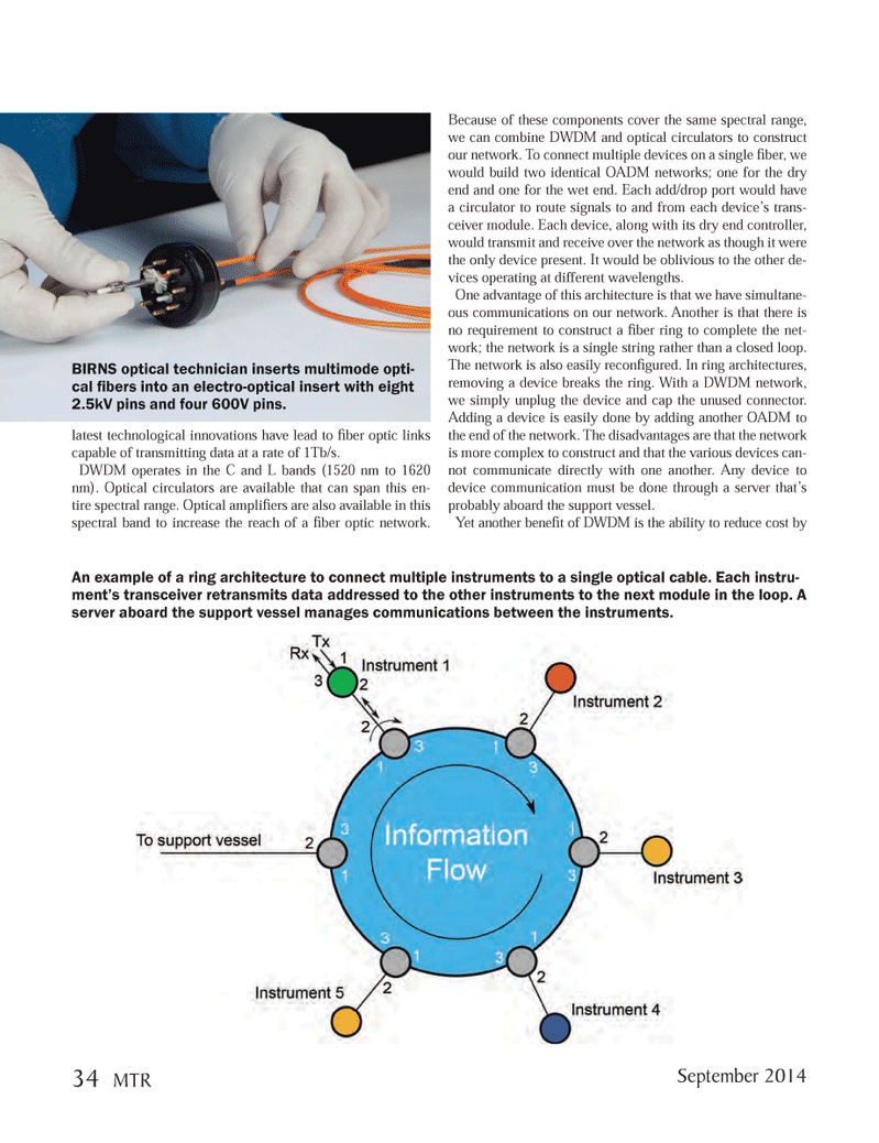
An example of a ring architecture to connect multiple instruments to a single optical cable. Each instru- ment’s transceiver retransmits data addressed to the other instruments to the next module in the loop. A server aboard the support vessel manages communications between the instruments.
BIRNS optical technician inserts multimode opti- cal fi bers into an electro-optical insert with eight 2.5kV pins and four 600V pins.
September 2014 34 MTR
MTR #7 (34-49).indd 34 8/27/2014 9:31:00 AM