
Page 14: of Marine Technology Magazine (Jan/Feb 2016)
Underwater Vehicle Annual: ROV, AUV, and UUVs
Read this page in Pdf, Flash or Html5 edition of Jan/Feb 2016 Marine Technology Magazine
 13
13
 15
15
Fiber Insights
Fiber Fundamentals
Multimode vs. Single Mode
By Ed Miskovic
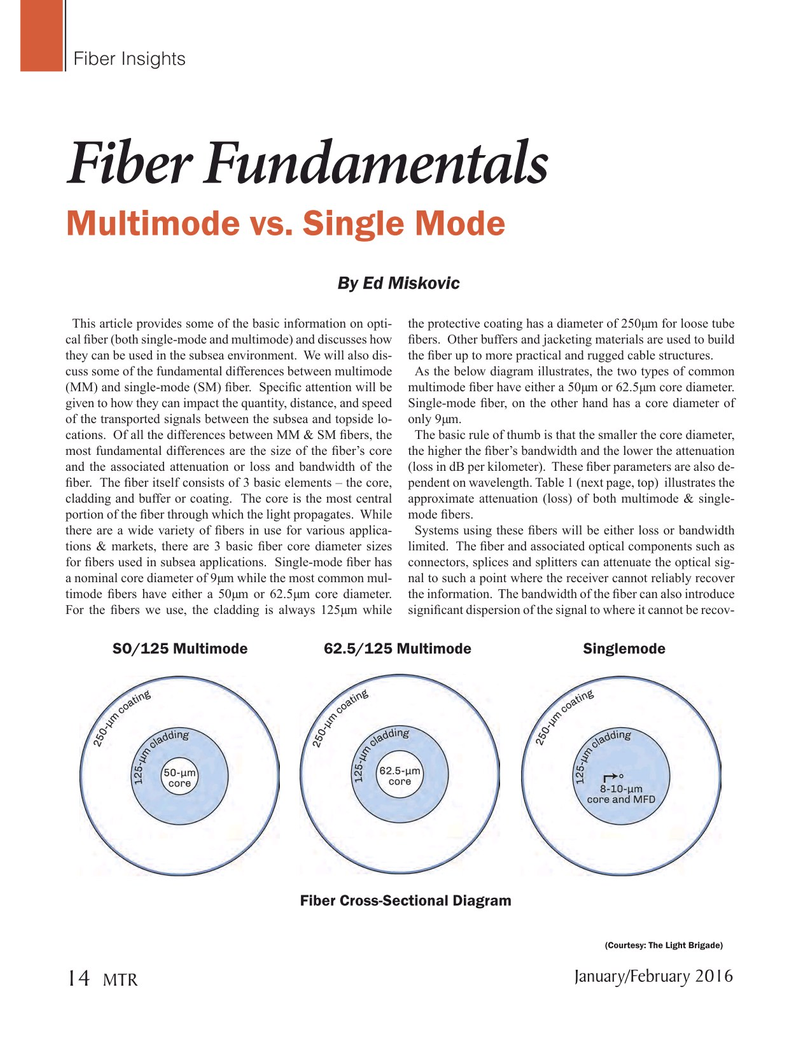
This article provides some of the basic information on opti- the protective coating has a diameter of 250µm for loose tube cal ? ber (both single-mode and multimode) and discusses how ? bers. Other buffers and jacketing materials are used to build they can be used in the subsea environment. We will also dis- the ? ber up to more practical and rugged cable structures. cuss some of the fundamental differences between multimode As the below diagram illustrates, the two types of common (MM) and single-mode (SM) ? ber. Speci? c attention will be multimode ? ber have either a 50µm or 62.5µm core diameter. given to how they can impact the quantity, distance, and speed Single-mode ? ber, on the other hand has a core diameter of of the transported signals between the subsea and topside lo- only 9µm. cations. Of all the differences between MM & SM ? bers, the The basic rule of thumb is that the smaller the core diameter, most fundamental differences are the size of the ? ber’s core the higher the ? ber’s bandwidth and the lower the attenuation and the associated attenuation or loss and bandwidth of the (loss in dB per kilometer). These ? ber parameters are also de- ? ber. The ? ber itself consists of 3 basic elements – the core, pendent on wavelength. Table 1 (next page, top) illustrates the cladding and buffer or coating. The core is the most central approximate attenuation (loss) of both multimode & single- portion of the ? ber through which the light propagates. While mode ? bers. there are a wide variety of ? bers in use for various applica- Systems using these ? bers will be either loss or bandwidth tions & markets, there are 3 basic ? ber core diameter sizes limited. The ? ber and associated optical components such as for ? bers used in subsea applications. Single-mode ? ber has connectors, splices and splitters can attenuate the optical sig- a nominal core diameter of 9µm while the most common mul- nal to such a point where the receiver cannot reliably recover timode ? bers have either a 50µm or 62.5µm core diameter. the information. The bandwidth of the ? ber can also introduce
For the ? bers we use, the cladding is always 125µm while signi? cant dispersion of the signal to where it cannot be recov- SO/125 Multimode 62.5/125 Multimode Singlemode
Fiber Cross-Sectional Diagram (Courtesy: The Light Brigade)
January/February 2016
MTR 14
MTR #1 (1-17).indd 14 1/21/2016 3:34:12 PM