
Page 20: of Marine Technology Magazine (Mar/Apr 2016)
Oceanographic Instrumentation: Measurement, Process & Analysis
Read this page in Pdf, Flash or Html5 edition of Mar/Apr 2016 Marine Technology Magazine
 19
19
 21
21
Fiber Insights temperature compensation in order to keep the wavelength so that the wavelength overall CWDM plan goes from 1271 to from drifting. The wavelength variation of these DFB lasers 1611nm instead of 1270 to 1610nm. CWDM and mux/demux as a function of temperature is on the order of 0.1nm/DegC. manufacturers may specify the wavelengths in either format.
The passband of the CWDM multiplexer and demultiplexer They are interchangeable. is on the order of 10nm to 13nm, depending on manufacturer and design. In addition, the absolute wavelength of the la- Bidirectional Transmission – CWDM technology offers an sers can vary by a couple nanometers. As such, the operating excellent platform for bidirectional transmission of a number temperature range of the lasers and transmission equipment of signals over one single-mode ? ber. In order to facilitate bi- is approximately 70 to 100 degC, typically around 80 degC. directional transmission of signals (e.g., Ethernet, data, etc.),
Taking into account the various component tolerances and the two wavelengths must be assigned – one for each direction of laser’s temperature drift, this results in an operating tempera- the signal. Using TDM (Time Division Multiplexing) each ture range of approximately -10 oC to +70 oC – well within wavelength can support a number of signals. For example, the range of subsea systems. DWDM systems, on the other using two wavelengths, you can transmit multiple videos as hand, require elaborate wavelength stabilization circuits to well as one direction of data or Ethernet while the second keep the laser’s wavelength from drifting at all as a function wavelength supports the return direction of the data. Since of temperature and performance variations. ? ber optics is signal agnostic, each wavelength can support
CWDM Multiplexer/Demultiplexer – CWDM mux/demux any type of signal from the simplest of a contact closure or devices are typically available in 4 or 8 channel increments. TTL to the more complex, high bandwidth HDSDI and GigE
The common bands are as follows: signals. A typical 8-ch CWDM mux/demux can support a sig-
Band 1 (4-channel) .............................1510 through 1570nm ni? cant amount of both unidirectional and bidirectional sig-
Band 2 (8-channel) ..............................1470 through 1610nm nals. These signals generally include the following: Analog
Band 3 (12-channel) ............................1310 through 1370nm video, HDSDI video, Ethernet (either 10/100 or GigE), data,
Band 4 (16-channel) ............................1270 through 1610nm and TTL. Depending on the ROV type and the speci? c mis-
All of these wavelength channels are separated in increments sion, other signals such as audio, USB and contacts might be of 20nm. Note that the individual wavelengths will be listed transmitted. as either even or odd wavelengths such as 1530nm or 1531nm.
The original CWDM wavelength plan had the lasers identi- System architecture – The optical transmission devices are ? ed with even wavelengths. In 2003 the ITU (International somewhat unique in CWDM & DWDM systems. From the
Telecommunications Union) revised the speci? cation by 1nm transmit standpoint, each of the CWDM lasers has a unique
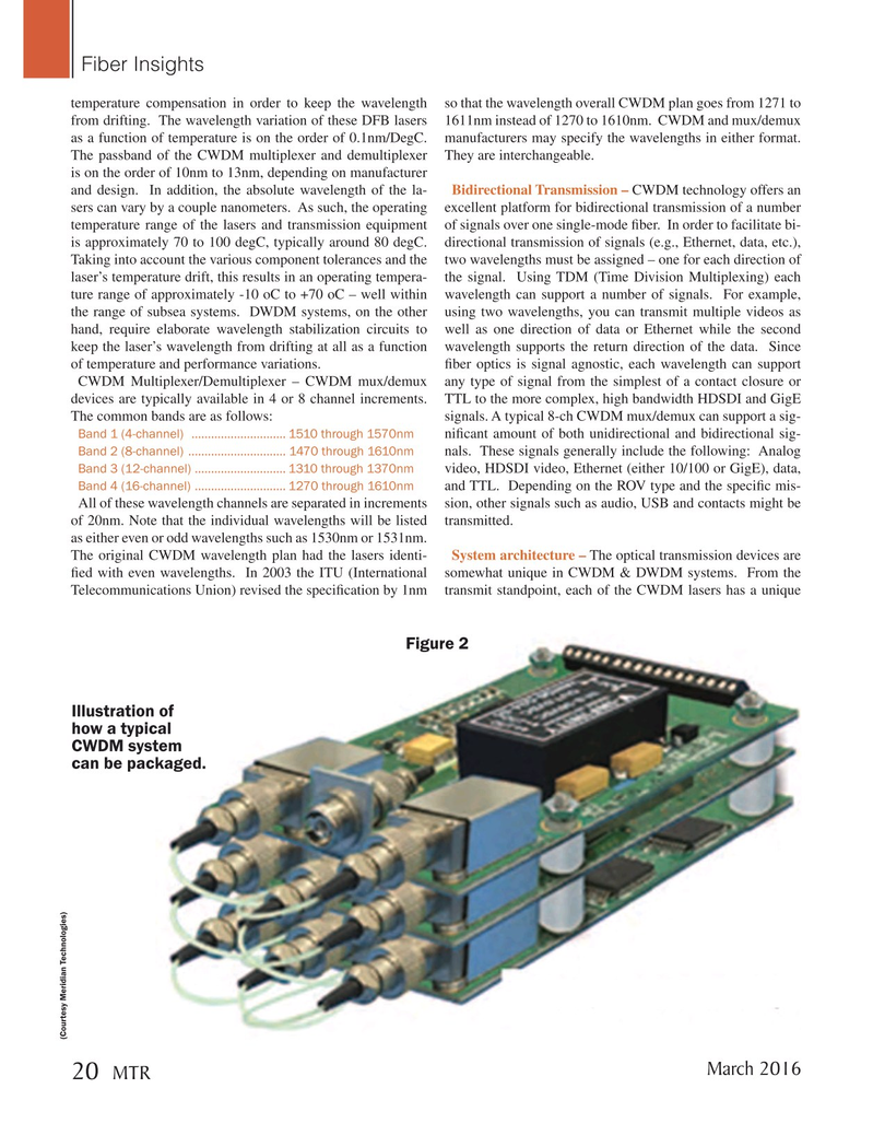
Figure 2
Illustration of how a typical
CWDM system can be packaged. (Courtesy Meridian Technologies)
March 2016 20 MTR
MTR #2 (18-33).indd 20 2/19/2016 11:01:20 AM