
Page 27: of Marine Technology Magazine (Mar/Apr 2016)
Oceanographic Instrumentation: Measurement, Process & Analysis
Read this page in Pdf, Flash or Html5 edition of Mar/Apr 2016 Marine Technology Magazine
 26
26
 28
28
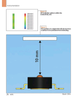
two factors—the intensity of the light operating at a duty cycle the LED is pe- controlling bio? lm growth, UVC LEDs and the length of exposure time. Dos- riodically turned on to deactivate DNA allow manufacturers to extend the dura- age is typically measured in milli-joules and then turned off to minimize power tion of in situ deployments in marine en- per centimeter squared (mJ/cm2) and consumption. The optimal duty cycle vironments while reducing maintenance is the product of UV intensity (in mW/ for a system is typically determined by costs. Integrating UVC LEDs into these cm2) and the exposure time (in sec- lab testing. The small footprint and high instruments for biofouling control is an onds). Industrial engineers and instru- brightness of UVC LEDs enables use in emerging trend that will become one ment designers use the relationship be- a variety of sensors, including remote of the mainstays of the industry in the tween these two parameters to develop monitoring in far areas of the world. By coming years. an effective system. Figures 2 and 3 show a volumetric protection example with a required UV dose of 10 mJ/cm2.
The cell has an external diameter of 10 mm and a length of 50 mm. Two UVC
LEDs, each emitting 2.5 mW, are used to achieve a fairly uniform intensity throughout the volume of the water in the cell to ensure that the full volume receives suf? cient UV light. As seen in
Figure 3 the irradiation pattern in this example is fairly uniform. However, it is important to note that it is the mini- mum, not the average, irradiance that engineers must consider for appropriate protection. In this example, 0.2 mW/ cm2 is the minimum irradiance of the system, so to achieve the target dose of 10 mJ/cm2 the cell requires a minimum exposure of 50 seconds.
Figure 4 shows an example of sur- face protection on a ? at surface 10 mm x 10 mm which requires a UV dose of 40 mJ/cm2. The intensity distribution on the surface depends on the distance between the UVC LED and the surface to be irradiated, the light output of the
LED, and the light emission pattern. In this example, the surface is 10 mm from the light source and the UVC LED emits 2.5 mW in a radiation pattern of 100 de-
Turbulence Instruments grees. Another critical design parameter is the repetitive cycling required for UV and Sensors irradiation. Speci? cally, cell division of colonized bacteria and colonization of fouling organisms happens during
Microstructure Turbulence the intervals between UV radiation ex-
AYEEE?Ž??GuAOŽY posures. So, in addition to the calcu- lated exposure time, designers need to consider the duty cycle for the LED as an important process parameter. Duty cycle is the percentage in one period in which an LED is turned on, for ex-
Visit us at. ample an LED operating at a 50% duty cycle would be turned on exactly half
KÐGAYŽuŽO?/YlG?YAOŽYAu of the time and off half of the time. By
ROCKLANDSCIENTIFIC.COM
Canadian Pavilion www.marinetechnologynews.com
Marine Technology Reporter 27
MTR #2 (18-33).indd 27 2/19/2016 11:15:44 AM