Page 50: of Marine Technology Magazine (September 2016)
Ocean Observation: Gliders, Buoys & Sub-Surface Networks
Read this page in Pdf, Flash or Html5 edition of September 2016 Marine Technology Magazine
Tech File
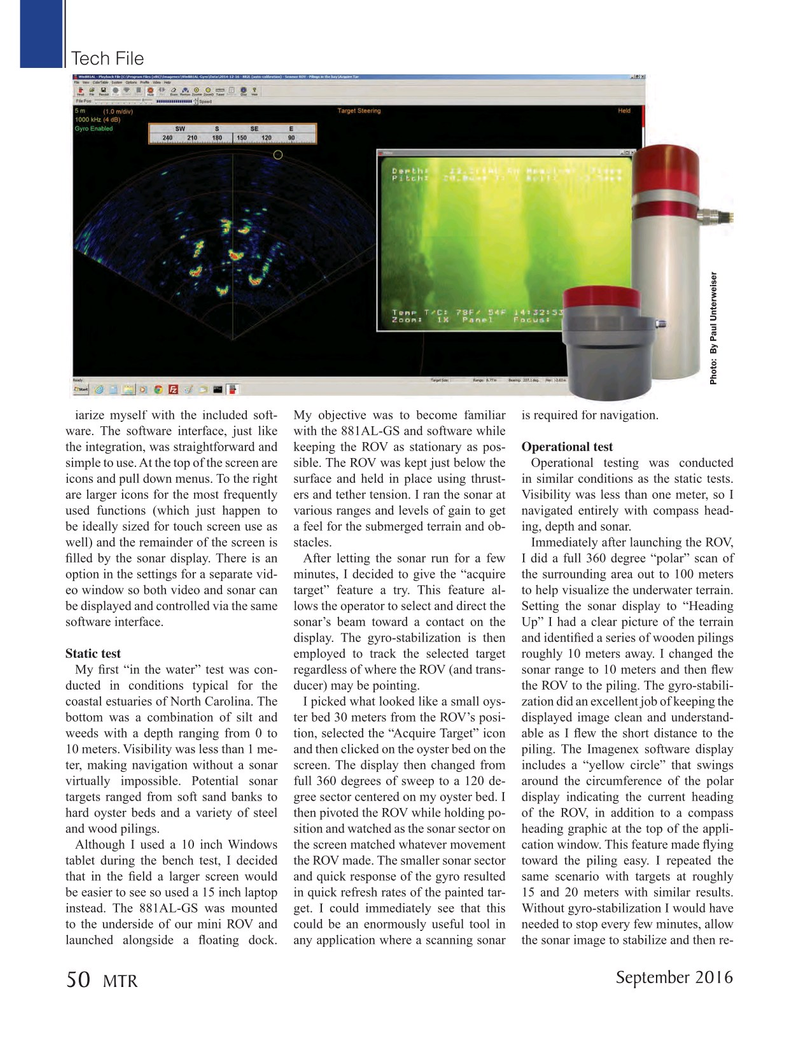
Photo: By Paul Unterweiser iarize myself with the included soft- My objective was to become familiar is required for navigation. ware. The software interface, just like with the 881AL-GS and software while the integration, was straightforward and keeping the ROV as stationary as pos- Operational test simple to use. At the top of the screen are sible. The ROV was kept just below the Operational testing was conducted icons and pull down menus. To the right surface and held in place using thrust- in similar conditions as the static tests. are larger icons for the most frequently ers and tether tension. I ran the sonar at Visibility was less than one meter, so I used functions (which just happen to various ranges and levels of gain to get navigated entirely with compass head- be ideally sized for touch screen use as a feel for the submerged terrain and ob- ing, depth and sonar.
well) and the remainder of the screen is stacles. Immediately after launching the ROV, ? lled by the sonar display. There is an After letting the sonar run for a few I did a full 360 degree “polar” scan of option in the settings for a separate vid- minutes, I decided to give the “acquire the surrounding area out to 100 meters eo window so both video and sonar can target” feature a try. This feature al- to help visualize the underwater terrain. be displayed and controlled via the same lows the operator to select and direct the Setting the sonar display to “Heading software interface. sonar’s beam toward a contact on the Up” I had a clear picture of the terrain display. The gyro-stabilization is then and identi? ed a series of wooden pilings
Static test employed to track the selected target roughly 10 meters away. I changed the
My ? rst “in the water” test was con- regardless of where the ROV (and trans- sonar range to 10 meters and then ? ew ducted in conditions typical for the ducer) may be pointing. the ROV to the piling. The gyro-stabili- coastal estuaries of North Carolina. The I picked what looked like a small oys- zation did an excellent job of keeping the bottom was a combination of silt and ter bed 30 meters from the ROV’s posi- displayed image clean and understand- weeds with a depth ranging from 0 to tion, selected the “Acquire Target” icon able as I ? ew the short distance to the 10 meters. Visibility was less than 1 me- and then clicked on the oyster bed on the piling. The Imagenex software display ter, making navigation without a sonar screen. The display then changed from includes a “yellow circle” that swings virtually impossible. Potential sonar full 360 degrees of sweep to a 120 de- around the circumference of the polar targets ranged from soft sand banks to gree sector centered on my oyster bed. I display indicating the current heading hard oyster beds and a variety of steel then pivoted the ROV while holding po- of the ROV, in addition to a compass and wood pilings. sition and watched as the sonar sector on heading graphic at the top of the appli-
Although I used a 10 inch Windows the screen matched whatever movement cation window. This feature made ? ying tablet during the bench test, I decided the ROV made. The smaller sonar sector toward the piling easy. I repeated the that in the ? eld a larger screen would and quick response of the gyro resulted same scenario with targets at roughly be easier to see so used a 15 inch laptop in quick refresh rates of the painted tar- 15 and 20 meters with similar results. instead. The 881AL-GS was mounted get. I could immediately see that this Without gyro-stabilization I would have to the underside of our mini ROV and could be an enormously useful tool in needed to stop every few minutes, allow launched alongside a ? oating dock. any application where a scanning sonar the sonar image to stabilize and then re-
September 2016
MTR 50
MTR #7 (50-64).indd 50 8/24/2016 2:37:45 PM

 49
49

 51
51
