Page 22: of Marine Technology Magazine (May/Jun 2022)
Read this page in Pdf, Flash or Html5 edition of May/Jun 2022 Marine Technology Magazine
 21
21
 23
23
LANDER LAB #3 BUOYANCY negative weight lifted by the vehicle from below. Too much of a ride on your lander. Placing the pods on the sides also reduces the lander lifted from the water may turn the lander into a log, the height under the A-frame, if that’s a consideration.
? oating horizontally. • Trim: An axis of symmetry runs through the centerline of
Stability of a lander is easier to establish than a glider or AUV the lander, top-to-bottom. The centerline points the way to the as the separation of the center of ? otation and the center of sea? oor and surface. Distribute positive and negative buoyancy gravity can be a signi? cant distance. The lander can be tall and uniformly around this axis. Position trim weights to balance as slender, like a spar buoy, with minimal frontal projected area in needed. A 2-lb transducer on one side, gets a 2-lb trim weight the direction of travel that causes drag. The long vertical length on the other side. Too much weight on one side will tip the land- enhances the intrinsic stability of the lander in all modes of op- er and force a glide angle away from the drop point, both down eration. and back, in some undetermined compass direction. We’ll dis-
Auxiliary buoyancy: These are side ? otation pods added to cuss recovery beacons in another issue.
increase net positive buoyancy for heavy payloads. These are • Water ? oat test: Begin where you want to end: the descent added in equal measure to both sides to maintain uniform trim. anchor gone, and the lander ? oating upright and stable on the
In our landers, we place the top of the side pods below the cen- surface, ? ag high, and the upper sphere half out of the water. A terline of the top sphere. This aids in lifting the upper hemi- dunk test off the stern of the boat before you leave the dock is a sphere out of the water for recovery. We have to add ? otation better place to ? nd a problem than on-station with everyone on in minimum increments of the spheres we have. If that adds too deck and the weather window closing. much ? otation, and the lander is sitting too high in the water, • A design tip: Keep the upper hemisphere of the top sphere we add additional counterweight to the bottom, also in equal as empty as possible. Restrict contents to recovery beacons that measure to each side. need to see or be seen. This limits the amount of weight that
Auxiliary side pods also provide space for additional batteries needs to be lifted above the water line on recovery. If heavier for lights, or instrumentation from research colleagues hitching elements are required, such as an acoustic release system, place
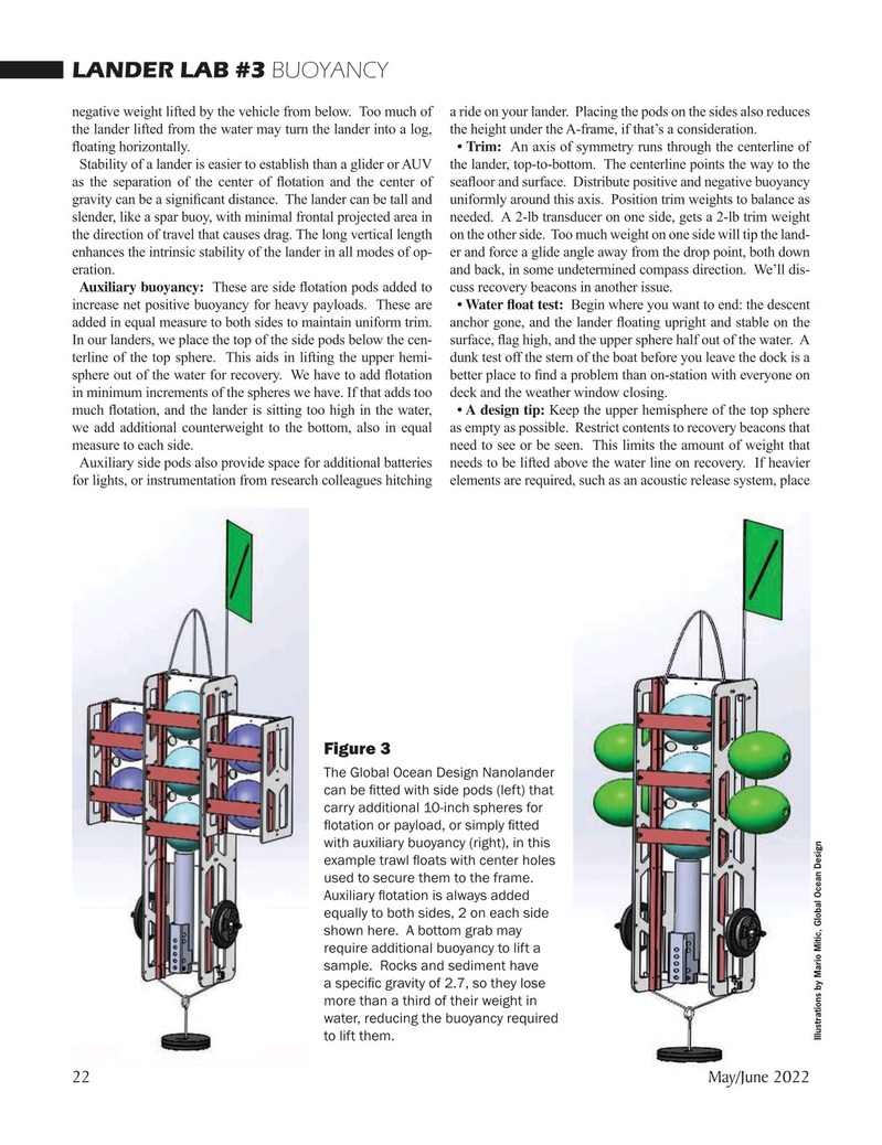
Figure 3
The Global Ocean Design Nanolander can be ? tted with side pods (left) that carry additional 10-inch spheres for ? otation or payload, or simply ? tted with auxiliary buoyancy (right), in this example trawl ? oats with center holes used to secure them to the frame.
Auxiliary ? otation is always added equally to both sides, 2 on each side shown here. A bottom grab may require additional buoyancy to lift a sample. Rocks and sediment have a speci? c gravity of 2.7, so they lose more than a third of their weight in water, reducing the buoyancy required
Illustrations by Mario Mitic, Global Ocean Design to lift them. 22 May/June 2022
MTR #4 (18-33).indd 22 4/25/2022 10:12:55 AM