
Page 10: of Maritime Reporter Magazine (January 15, 1969)
Read this page in Pdf, Flash or Html5 edition of January 15, 1969 Maritime Reporter Magazine
 9
9
 11
11
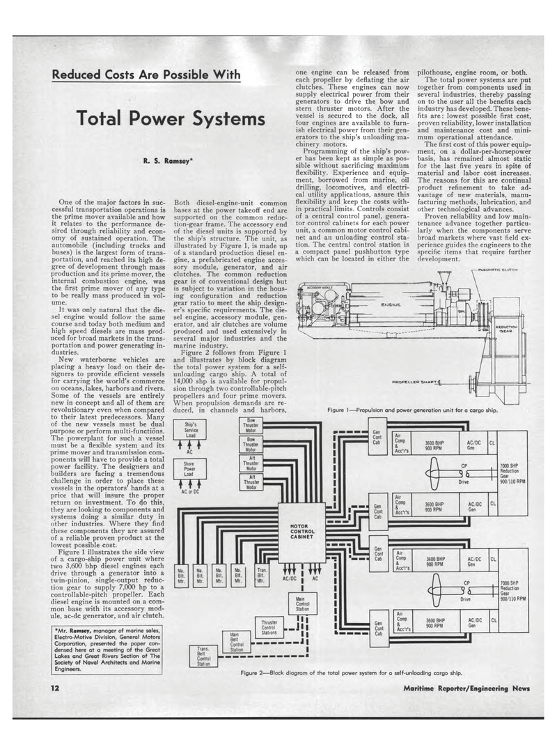
Reduced Costs Are Possible With Total Power Systems R. S. Ramsey* One of the major factors in suc-cessful transportation operations is the prime mover available and how it relates to the performance de-sired through reliability and econ-omy of sustained operation. The automobile (including trucks and buses) is the largest form of trans-portation, and reached its high de-gree of development through mass production and its prime mover, the internal combustion engine, was the first prime mover of any type to be really mass produced in vol-ume. It was only natural that the die-sel engine would follow the same course and today both medium and high speed diesels are mass prod-uced for broad markets in the trans-portation and power generating in-dustries. New waterborne vehicles are placing a heavy load on their de-signers to provide efficient vessels for carrying the world's commerce on oceans, lakes, harbors and rivers. Some of the vessels are entirely new in concept and all of them are revolutionary even when compared to their latest predecessors. Many of the new vessels must be dual purpose or perform multi-functions. The powerplant for such a vessel must be a flexible system and its prime mover and transmission com-ponents will have to provide a total power facility. The designers and builders are facing a tremendous challenge in order to place these vessels in the operators' hands at a price that will insure the proper return on investment. To do this, they are looking to components and systems doing a similar duty in other industries. Where they find these components they are assured of a reliable proven product at the lowest possible cost. Figure 1 illustrates the side view of a cargo-ship power unit where two 3,600 bhp diesel engines each drive through a generator into a twin-pinion, single-output reduc-tion gear to supply 7,000 hp to a controllable-pitch propeller. Each diesel engine is mounted on a com-mon base with its accessory mod-ule, ac-dc generator, and air clutch. *Mr. Ramsey, manager of marine sales, Electro-Motive Division, General Motors Corporation, presented the paper con-densed here at a meeting of the Great Lakes and Great Rivers Section of The Society of Naval Architects and Marine Engineers. Both diesel-engine-unit common bases at the power takeoff end are supported on the common reduc-tion-gear frame. The accessory end of the diesel units is supported by the ship's structure. The unit, as illustrated by Figure 1, is made up of a standard production diesel en-gine, a prefabricated engine acces-sory module, generator, and air clutches. The common reduction gear is of conventional design but is subject to variation in the hous-ing configuration and reduction gear ratio to meet the ship design-er's specific requirements. The die-sel engine, accessory module, gen-erator, and air clutches are volume produced and used extensively in several major industries and the marine industry. Figure 2 follows from Figure 1 and illustrates by block diagram the total power system for a self-unloading cargo ship. A total of 14,000 shp is available for propul-sion through two controllable-pitch propellers and four prime movers. When propulsion demands are re-duced, in channels and harbors, one engine can be released from each propeller by deflating the air clutches. These engines can now supply electrical power from their generators to drive the bow and stern thruster motors. After the vessel is secured to the dock, all four engines are available to furn-ish electrical power from their gen-erators to the ship's unloading ma-chinery motors. Programming of the ship's pow-er has been kept as simple as pos-sible without sacrificing maximum flexibility. Experience and equip-ment, borrowed from marine, oil drilling, locomotives, and electri-cal utility applications, assure this flexibility and keep the costs with-in practical limits. Controls consist of a central control panel, genera-tor control cabinets for each power unit, a common motor control cabi-net and an unloading control sta-tion. The central control station is a compact panel pushbutton type which can be located in either the pilothouse, engine room, or both. The total power systems are put together from components used in several industries, thereby passing on to the user all the benefits each industry has developed. These bene-fits are: lowest possible first cost, proven reliability, lower installation and maintenance cost and mini-mum operational attendance. The first cost of this power equip-ment, on a dollar-per-horsepower basis, has remained almost static for the last five years in spite of material and labor cost increases. The reasons for this are continual product refinement to take ad-vantage of new materials, manu-facturing methods, lubrication, and other technological advances. Proven reliability and low main-tenance advance together particu-larly when the components serve broad markets where vast field ex-perience guides the engineers to the specific items that require further development. PUEUMATIC CLUTCH PROPELLER SHAFT Figure 1?Propulsion and power generation unit for a cargo ship. a Air Comp & Acc'r's 3600 BJNP 900 RPM AC/DC Gen CL c \ Cp i c -1 ? 1 c u Drive Air Comp & Acc'r's 3600 BHP 900 RPM AC/DC Gen CL u 7000 SHP Reduction Gear 900/110 RPM Ma Ma Ma. Ma. Tran. Bit Bit. Bit. Bit. Bit. Mtr. Mtr. Mtr. Mtr. 'Mtr. w\w AC/DC 3600 BHP 900 RPM AC/DC Gen CL CP Drive Gen Cont Cab Aif Comp & Acc'r's 3600 BHP 900 RPM AC/DC Gen CL 7000 SHP Reduction Gear 900/110 RPM Figure 2?Block diagram of the total power system for a self-unloading cargo ship. 12 Maritime Reporter/Engineering News
