Page 36: of Maritime Reporter Magazine (January 15, 1969)
Read this page in Pdf, Flash or Html5 edition of January 15, 1969 Maritime Reporter Magazine
 35
35
 37
37
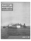
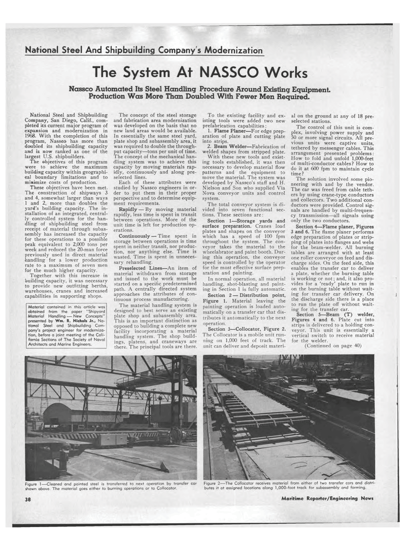
National Steel And Shipbuilding Company s Modernization The System At NASSCO Works Nassco Automated Its Steel Handling Procedure Around Existing Equipment. Production Was More Than Doubled With Fewer Men Required. National Steel and Shipbuilding Company, San Diego, Calif., com-pleted its current major program of expansion and modernization in 1968. With the completion of this program, Nasseo has more than doubled its shipbuilding capacity and is now ranked as one of the largest U.S. shipbuilders. The ab.jeetives of this program were to achieve the maximum building capacity within geographi-cal boundary limitations and to minimize costs of production. These objectives have been met. The construction of shipways 3 and 4, somewhat larger than ways 1 and 2, more than doubles the yard's building capacity. The in-stallation of an integrated, central-ly controlled system for the han-dling of shipbuilding steel from receipt of material through subas-sembly has increased the capacity for these operations to a possible peak equivalent to 2,000 tons per week and reduced the 20-man force previously used in direct material handling for a lower production rate to a maximum of seven meti for the much higher capacity. Together with this increase in building capacity, it was necessary to provide new outfitting berths, warehouses, cranes and increased capabilities in supporting shops. Material contained in this article was obtained from the paper "Shipyard Material Handling ? New Concepts" presented by Wm. R. Nichols Jr., Na-tional Steel and Shipbuilding Com-pany's project engineer for moderniza-tion, before a joint meeting of the Cali-fornia Sections of The Society of Naval Architects and Marine Engineers. The concept of the steel storage and fabrication area modernization was developed on the basis that no new land areas would be available. In essentially the same steel yard, plate shop and subassembly area, it was required to double the through-put capacity?tons per unit of time. The concept of the mechanical han-dling system was to achieve this capacity by moving materials rap-idly, continuously and along pre-selected lines. Each of these attributes were studied by Nassco engineers in or-der to put them in their proper perspective and to determine equip-ment requirements. Rapidly ? By moving material rapidly, less time is spent in transit between operations. More of the unit time is left for production op-erations. Continuously ? Time spent in storage between operations is time spent in neither transit, nor produc-tion, nor anything else. Time is wasted. Time is spent in unneces-sary rehandling. Preselected Lines?An item of material withdrawn from storage and issued to the work must be started on a specific predetermined path. A centrally directed system approaches the attributes of con-tinuous process manufacturing. The material handling system is designed to best serve an existing plate shop and subassembly area. This is an important distinction as opposed to building a complete new facility incorporating a material handling system. The shop build-ings, platens, and craneways are there. The principal tools are there. To the existing facility and ex-isting tools were added two new prefabrication capabilities: 1. Flame Planer?For edge prep-aration of plate and cutting plate into strips. 2. Beam Welder?Fabrication of welded shapes from stripped plate. With these new tools and exist-ing tools established, it was then necessary to develop material flow patterns and the equipment to move the material. The system was developed by Nassco's staff and H. Nielson and Son who supplied Via Nova conveyor units and control system. The total conveyor system is di-vided into seven functional sec-tions. These sections are: Section 1?Storage yards and surface preparation. Cranes load plates and shapes on the conveyor which has a speed of 100 fpm throughout the system. The con-veyor takes the material to the wheelabrator and paint booth. Dur-ing this operation, the conveyor speed is controlled by the operator for the most effective surface prep-aration and painting. In normal operation, all material handling, shot-blasting and paint-ing in Section 1 is fully automatic. Section 2 ? Distribution point, Figure 1. Material leaving the painting operation is loaded auto-matically on a transfer car that dis-tributes it automatically to the next operation. Section 3?Collocator, Figure 2. The Collocator is a mobile unit run-ning on 1,000 feet of track. The unit can deliver and deposit materi-al on the ground at any of 18 pre-selected stations. The control of this unit is com-plex, involving power supply and 50 or more signal circuits. All pre-vious units were captive units, tethered by messenger cables. This arrangement presented problems: How to fold and unfold 1,000-feet of multi-conductor cables? How to do it at 600 fpm to maintain cycle time ? The solution involved some pio-neering with and by the vendor. The car was freed from cable teth-ers by using crane-type conductors and collectors. Two additional con-ductors were provided. Control sig-nals are handled by multi-frequen-cy transmission?all signals using only the two conductors. Section 4?Flame planer, Figures 3 and 6. The flame planer performs edge preparation of plates or strip-ping of plates into flanges and webs for the beam-welder. All burning tables are arranged with at least one roller conveyor on feed and dis-charge sides. On the feed side, this enables the transfer car to deliver a plate, whether the burning table is working or not; and, it also pro-vides for a 'ready' plate to run in on the burning table without wait-ing for transfer car delivery. On the discharge side there is a place to run the plate off without wait-ing for the transfer car. Section 5?Beam (T) welder, Figures 4 and 6. Plate cut into strips is delivered to a holding con-veyor. This unit is essentially a vertical switch to receive material for the welder. (Continued on page 40) Figure 1?Cleaned and painted steel is transferred to next operation by transfer car Figure 2?The Collocator receives material from either of two transfer cars and distri shown above. The material goes either to burning operations or to Collocator. butes it at assigned locations along 1,000-foot track for subassembly and forming. 38 Maritime Reporter/Engineering News
