Page 38: of Maritime Reporter Magazine (January 15, 1969)
Read this page in Pdf, Flash or Html5 edition of January 15, 1969 Maritime Reporter Magazine
 37
37
 39
39
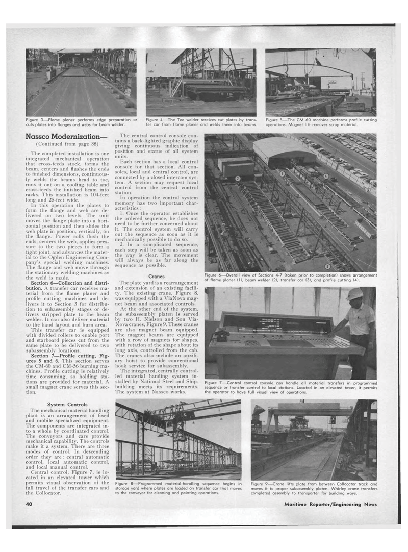
Figure 3?Flame planer performs edge preparation or Figure 4?The Tee welder receives cut plates by trans- Figure 5?The CM 60 machine performs profile cutting cuts plates into flanges and webs for beam welder. fer car from flame planer and welds them into beams. operations. Magnet lift removes scrap material. Nassco Modernization? (Continued from page 38) The completed installation is one integrated mechanical operation that cross-feeds stock, forms the beam, centers and flushes the ends to finished dimensions, continuous-ly welds the beams head to toe, runs it out on a cooling table and cross-feeds the finished beam into racks. This installation is 104-feet long and 25-feet wide. In this operation the plates to form the flange and web are de-livered on two levels. The unit moves the flange plate into a hori-zontal position and then slides the web plate in position, vertically, on the flange. Power rolls flush the ends, centers the web, applies pres-sure to the two pieces to form a tight joint, and advances the mater-ial to the Ogden Engineering Com-pany's special welding machines. The flange and web move through the stationary welding machines as the weld is made. Section 6?Collection and distri-bution. A transfer car receives ma-terial from the flame planer and profile cutting machines and de-livers it to Section 3 for distribu-tion to subassembly stages or de-livers stripped plate to the beam welder. It can also deliver material to the hand layout and burn area. This transfer car is equipped with divided rollers to enable port and starboard pieces cut from the same plate to be delivered to two subassembly locations. Section 7?Profile cutting, Fig-ures 5 and 6. This section serves the CM-60 and CM-56 burning ma-chines. Profile cutting is relatively time consuming, so holding sta-tions are provided for material. A small magnet crane serves this sec-tion. The central control console con-tains a back-lighted graphic display giving continuous indication of position and status of all system units. Each section has a local control console for that section. All con-soles, local and central control, are connected by a closed intercom sys-tem. A section may request local control from the central control station. In operation the control system memory has two important char-acteristics : 1. Once the operator establishes the ordered sequence, he does not need to be further concerned about it. The control system will carry out the sequence as soon as it is mechanically possible to do so. 2. In a complicated sequence, each step will be taken as soon as the way is clear. The movement will always be as far along the sequence as possible. Cranes The plate yard is a rearrangement and extension of an existing facili-ty. The existing crane, Figure 8. was equipped with a ViaNova mag-net beam and associated controls. At the other end of the system, the subassembly platen is served by two H. Nielson and Son Via-Nova cranes, Figure 9. These cranes are also magnet beam equipped. The magnet beams are equipped with a row of magnets for shapes, with rotation of the shape about its long axis, controlled from the cab. The cranes also include an auxili-ary hoist to provide conventional hook service for subassembly. The integrated, centrally control-led material handing system in-stalled by National Steel and Ship-building meets its requirements. The system at Nassco works. Figure 7?Central control console can handle all material transfers in programmed sequence or transfer control to local stations. Located in an elevated tower, it permits the operator to have full visual view of operations. System Controls The mechanical material handling plant is an arrangement of fixed and mobile specialized equipment. The components are integrated in-to a whole by coordinated control. The conveyors and cars provide mechanical capability. The controls make it a system. There are three modes of control. In descending order they are: central automatic control, local automatic control, and local manual control. Central control, Figure 7, is lo-cated in an elevated tower which permits visual observation of the full travel of the transfer cars and the Collocator. Figure 8?Programmed material-handling sequence begins in storage yard where plates are loaded on transfer car that moves to the conveyor for cleaning and painting operations. Figure 9?Crane lifts plate from between Collocator track and moves it to proper subassembly platen. Whirley crane transfers completed assembly to transporter for building ways. Figure 6?Overall view of Sections 4-7 (taken prior to completion) shows arrangement of flame planer (1), beam welder (2), transfer car (3), and profile cutting (4). 40 Maritime Reporter/Engineering News
