Page 24: of Maritime Reporter Magazine (June 15, 1969)
Read this page in Pdf, Flash or Html5 edition of June 15, 1969 Maritime Reporter Magazine
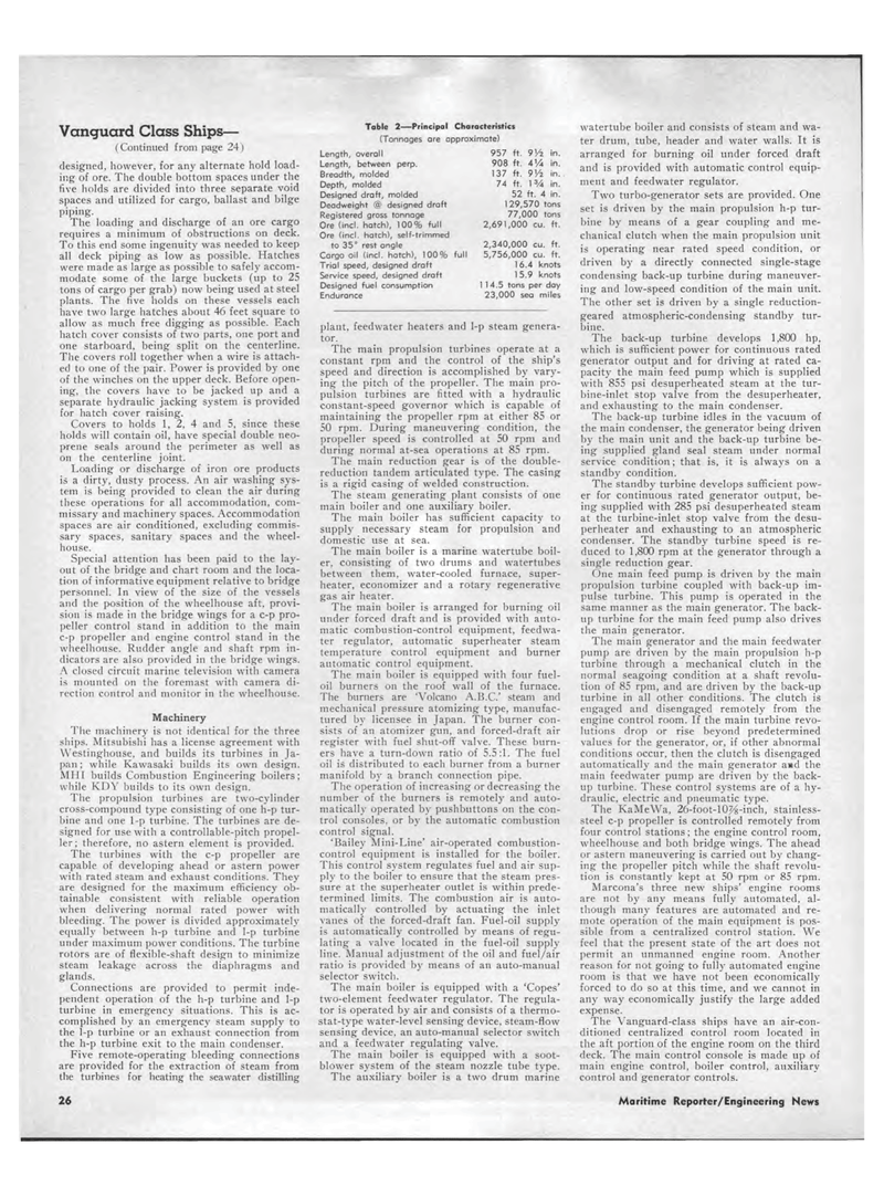
Vanguard Class Ships? (Continued from page 24) designed, however, for any alternate hold load-ing of ore. The double bottom spaces under the five holds are divided into three separate void spaces and utilized for cargo, ballast and bilge piping. The loading and discharge of an ore cargo requires a minimum of obstructions on deck. To this end some ingenuity was needed to keep all deck piping as low as possible. Hatches were made as large as possible to safely accom-modate some of the large buckets (up to 25 tons of cargo per grab) now being used at steel plants. The five holds on these vessels each have two large hatches about 46 feet square to allow as much free digging as possible. Each hatch cover consists of two parts, one port and one starboard, being split on the centerline. The covers roll together when a wire is attach-ed to one of the pair. Power is provided by one of the winches on the upper deck. Before open-ing, the covers have to be jacked up and a separate hydraulic jacking system is provided for hatch cover raising. Covers to holds 1, 2, 4 and 5, since these holds will contain oil, have special double neo-prene seals around the perimeter as well as on the centerline joint. Loading or discharge of iron ore products is a dirty, dusty process. An air washing sys-tem is being provided to clean the air during these operations for all accommodation, com-missary and machinery spaces. Accommodation spaces are air conditioned, excluding commis-sary spaces, sanitary spaces and the wheel-house. Special attention has been paid to the lay-out of the bridge and chart room and the loca-tion of informative equipment relative to bridge personnel. In view of the size of the vessels and the position of the wheelhouse aft, provi-sion is made in the bridge wings for a c-p pro-peller control stand in addition to the main c-p propeller and engine control stand in the wheelhouse. Rudder angle and shaft rpm in-dicators are also provided in the bridge wings. A closed circuit marine television with camera is mounted on the foremast with camera di-rection control and monitor in the wheelhouse. Machinery The machinery is not identical for the three ships. Mitsubishi has a license agreement with Westinghouse, and builds its turbines in Ja-pan ; while Kawasaki builds its own design. MHI builds Combustion Engineering boilers; while KDY builds to its own design. The propulsion turbines are two-cylinder cross-compound type consisting of one h-p tur-bine and one 1-p turbine. The turbines are de-signed for use with a controllable-pitch propel-ler; therefore, no astern element is provided. The turbines with the c-p propeller are capable of developing ahead or astern power with rated steam and exhaust conditions. They are designed for the maximum efficiency ob-tainable consistent with reliable operation when delivering normal rated power with bleeding. The power is divided approximately equally between h-p turbine and 1-p turbine under maximum power conditions. The turbine rotors are of flexible-shaft design to minimize steam leakage across the diaphragms and glands. Connections are provided to permit inde-pendent operation of the h-p turbine and 1-p turbine in emergency situations. This is ac-complished by an emergency steam supply to the 1-p turbine or an exhaust connection from the h-p turbine exit to the main condenser. Five remote-operating bleeding connections are provided for the extraction of steam from the turbines for heating the seawater distilling Table 2?Principal Characteristics (Tonnages are approximate) Length, overall 957 ft. 9V2 in. Length, between perp. 908 ft. AVA in. Breadth, molded 137 ft. 9Vz in. Depth, molded 74 ft. 1 VA in. Designed draft, molded 52 ft. 4 in. Deadweight @ designed draft 129,570 tons Registered gross tonnage 77,000 tons Ore (incl. hatch), 100% full 2,691,000 cu. ft. Ore (incl. hatch), self-trimmed to 35° rest angle 2,340,000 cu. ft. Cargo oil (incl. hatch), 100% full 5,756,000 cu. ft. Trial speed, designed draft 16.4 knots Service speed, designed draft 15.9 knots Designed fuel consumption 114.5 tons per day Endurance 23,000 sea miles plant, feedwater heaters and 1-p steam genera-tor. The main propulsion turbines operate at a constant rpm and the control of the ship's speed and direction is accomplished by vary-ing the pitch of the propeller. The main pro-pulsion turbines are fitted with a hydraulic constant-speed governor which is capable of maintaining the propeller rpm at either 85 or 50 rpm. During maneuvering condition, the propeller speed is controlled at 50 rpm and during normal at-sea operations at 85 rpm. The main reduction gear is of the double-reduction tandem articulated type. The casing is a rigid casing of welded construction. The steam generating plant consists of one main boiler and one auxiliary boiler. The main boiler has sufficient capacity to supply necessary steam for propulsion and domestic use at sea. The main boiler is a marine watertube boil-er. consisting of two drums and watertubes between them, water-cooled furnace, super-heater, economizer and a rotary regenerative gas air heater. The main boiler is arranged for burning oil under forced draft and is provided with auto-matic combustion-control equipment, feedwa-ter regulator, automatic superheater steam temperature control equipment and burner automatic control equipment. The main boiler is equipped with four fuel-oil burners on the roof wall of the furnace. The burners are 'Volcano A.B.C.' steam and mechanical pressure atomizing type, manufac-tured by licensee in Japan. The burner con-sists of an atomizer gun, and forced-draft air register with fuel shut-off valve. These burn-ers have a turn-down ratio of 5.5:1. The fuel oil is distributed to each burner from a burner manifold by a branch connection pipe. The operation of increasing or decreasing the number of the burners is remotely and auto-matically operated by pushbuttons on the con-trol consoles, or by the automatic combustion control signal. 'Bailey Mini-Line' air-operated combustion-control equipment is installed for the boiler. This control system regulates fuel and air sup-ply to the boiler to ensure that the steam pres-sure at the superheater outlet is within prede-termined limits. The combustion air is auto-matically controlled by actuating the inlet vanes of the forced-draft fan. Fuel-oil supply is automatically controlled by means of regu-lating a valve located in the fuel-oil supply line. Manual adjustment of the oil and fuel/air ratio is provided by means of an auto-manual selector switch. The main boiler is equipped with a 'Copes' two-element feedwater regulator. The regula-tor is operated by air and consists of a thermo-stat-type water-level sensing device, steam-flow sensing device, an auto-manual selector switch and a feedwater regulating valve. The main boiler is equipped with a soot-blower system of the steam nozzle tube type. The auxiliary boiler is a two drum marine watertube boiler and consists of steam and wa-ter drum, tube, header and water walls. It is arranged for burning oil under forced draft and is provided with automatic control equip-ment and feedwater regulator. Two turbo-generator sets are provided. One set is driven by the main propulsion h-p tur-bine by means of a gear coupling and me-chanical clutch when the main propulsion unit is operating near rated speed condition, or driven by a directly connected single-stage condensing back-up turbine during maneuver-ing and low-speed condition of the main unit. The other set is driven by a single reduction-geared atmospheric-condensing standby tur-bine. The back-up turbine develops 1,800 hp, which is sufficient power for continuous rated generator output and for driving at rated ca-pacity the main feed pump which is supplied with 855 psi desuperheated steam at the tur-bine-inlet stop valve from the desuperheater, and exhausting to the main condenser. The back-up turbine idles in the vacuum of the main condenser, the generator being driven by the main unit and the back-up turbine be-ing supplied gland seal steam under normal service condition; that is, it is always on a standby condition. The standby turbine develops sufficient pow-er for continuous rated generator output, be-ing supplied with 285 psi desuperheated steam at the turbine-inlet stop valve from the desu-perheater and exhausting to an atmospheric condenser. The standby turbine speed is re-duced to 1,800 rpm at the generator through a single reduction gear. One main feed pump is driven by the main propulsion turbine coupled with back-up im-pulse turbine. This pump is operated in the same manner as the main generator. The back-up turbine for the main feed pump also drives the main generator. The main generator and the main feedwater pump are driven by the main propulsion h-p turbine through a mechanical clutch in the normal seagoing condition at a shaft revolu-tion of 85 rpm, and are driven by the back-up turbine in all other conditions. The clutch is engaged and disengaged remotely from the engine control room. If the main turbine revo-lutions drop or rise beyond predetermined values for the generator, or, if other abnormal conditions occur, then the clutch is disengaged automatically and the main generator awd the main feedwater pump are driven by the back-up turbine. These control systems are of a hy-draulic, electric and pneumatic type. The KaMeWa, 26-foot-10%-inch, stainless-steel c-p propeller is controlled remotely from four control stations ; the engine control room, wheelhouse and both bridge wings. The ahead or astern maneuvering is carried out by chang-ing the propeller pitch while the shaft revolu-tion is constantly kept at 50 rpm or 85 rpm. Marcona's three new ships' engine rooms are not by any means fully automated, al-though many features are automated and re-mote operation of the main equipment is pos-sible from a centralized control station. We feel that the present state of the art does not permit an unmanned engine room. Another reason for not going to fully automated engine room is that we have not been economically forced to do so at this time, and we cannot in any way economically justify the large added expense. The Vanguard-class ships have an air-con-ditioned centralized control room located in the aft portion of the engine room on the third deck. The main control console is made up of main engine control, boiler control, auxiliary control and generator controls. 26 Maritime Reporter/Engineering News

 23
23

 25
25
