Page 37: of Maritime Reporter Magazine (March 1971)
Read this page in Pdf, Flash or Html5 edition of March 1971 Maritime Reporter Magazine
Sperry Demonstrates
Integrated Navigation
With the trend toward more and larger vessels with reduced manpow- er, navigation and safety problems have become more acute. This trend has necessitated the development of new equipment and system concepts to improve navigation accuracy and increase efficiency.
At a recent demonstration held at the Seamen's Church Institute in
New York City, the Sperry Marine
Systems Division of the Sperry Rand
Corporation demonstrated its ap- proach to satisfying this need. The method proposed revolves around a building-block concept whereby basic elements are combined in a system configuration that permits outfitting any vessel to any level of complexity consistent with the vessel require- ments with the assurance that new requirements can be met in the future by expanding the initial system.
In the area of navigation, such a systems approach involves all the navigation instruments aboard a ves- sel, managed in a system configura- tion that derives the most accurate and reliable navigation information required.
A general-purpose digital computer is employed to tie together the vari- ous navigation equipment, thereby permitting an analytical approach to optimize each piece of navigation data. By the proper use of time- sharing, cross-correction of instru- ment data, and the use of computer- derived weighting factors, maximum navigation accuracy can be obtained with a minimum of physical hard- ware.
The size of Sperry's Integrated
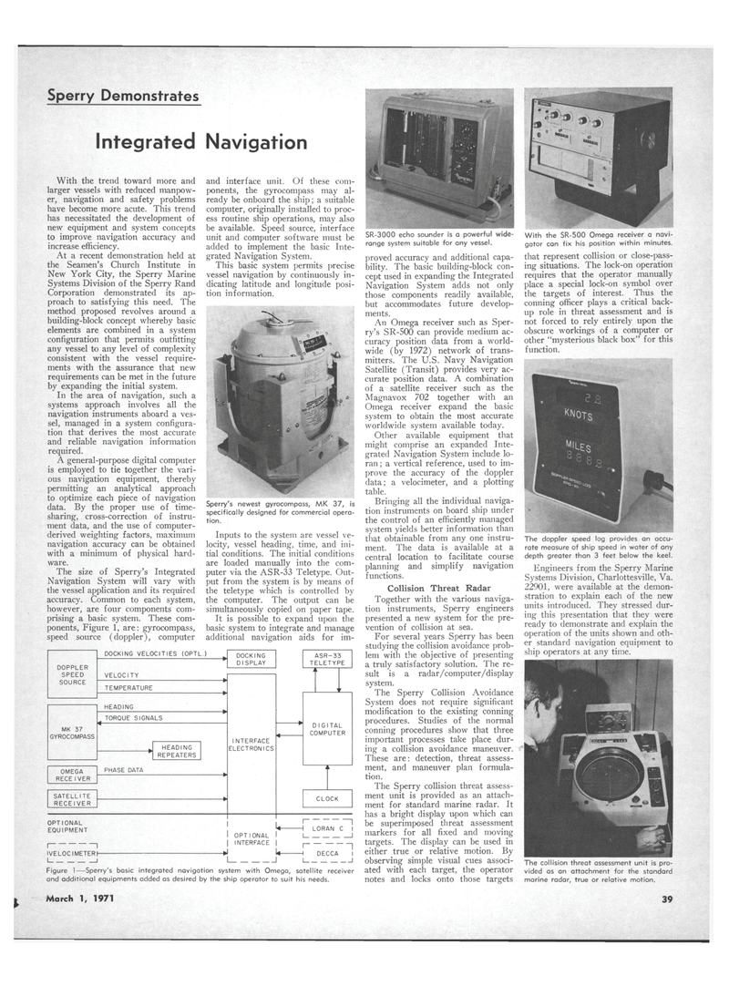
Navigation System will vary with the vessel application and its required accuracy. Common to each system, however, are four components com- prising a basic system. These com- ponents, Figure 1, are: gyrocompass, speed source (doppler), computer and interface unit. Of these com- ponents, the gyrocompass may al- ready be onboard the ship; a suitable computer, originally installed to proc- ess routine ship operations, may also be available. Speed source, interface unit and computer software must be added to implement the basic Inte- grated Navigation System.
This basic system permits precise vessel navigation by continuously in- dicating latitude and longitude posi- tion information.
Sperry's newest gyrocompass, MK 37, is specifically designed for commercial opera- tion.
Inputs to the system are vessel ve- locity, vessel heading, time, and ini- tial conditions. The initial conditions are loaded manually into the com- puter via the ASR-33 Teletype. Out- put from the system is by means of the teletype which is controlled by the computer. The output can be simultaneously copied on paper tape.
It is possible to expand upon the basic system to integrate and manage additional navigation aids for im-
SR-3000 echo sounder is a powerful wide- range system suitable for any vessel. proved accuracy and additional capa- bility. The basic building-block con- cept used in expanding the Integrated
Navigation System adds not only those components readily available, but accommodates future develop- ments.
An Omega receiver such as Sper- ry's SR-500 can provide medium ac- curacy position data from a world- wide (by 1972) network of trans- mitters. The U.S. Navy Navigation
Satellite (Transit) provides very ac- curate position data. A combination of a satellite receiver such as the
Magnavox 702 together with an
Omega receiver expand the basic system to obtain the most accurate worldwide system available today.
Other available equipment that might comprise an expanded Inte- grated Navigation System include lo- ran; a vertical reference, used to im- prove the accuracy of the doppler data; a velocimeter, and a plotting table.
Bringing all the individual naviga- tion instruments on board ship under the control of an efficiently managed system yields better information than that obtainable from any one instru- ment. The data is available at a central location to facilitate course planning and simplify navigation functions.
Collision Threat Radar
Together with the various naviga- tion instruments, Sperry engineers presented a new system for the pre- vention of collision at sea.
For several years Sperry has been studying the collision avoidance prob- lem with the objective of presenting a truly satisfactory solution. The re- sult is a radar/computer/display system.
The Sperry Collision Avoidance
System does not require significant modification to the existing conning procedures. Studies of the normal conning procedures show that three important processes take place dur- ing a collision avoidance maneuver.
These are: detection, threat assess- ment, and maneuver plan formula- tion.
The Sperry collision threat assess- ment unit is provided as an attach- ment for standard marine radar. It has a bright display upon which can be superimposed threat assessment markers for all fixed and moving targets. The display can be used in either true or relative motion. By observing simple visual cues associ- ated with each target, the operator notes and locks onto those targets
DOPPLER
SPEED
SOURCE
MK 37
GYROCOMPASS
OMEGA
RECEIVER
SATELLITE
RECEIVER
DOCKING VELOCITIES (OPTL.)
VELOCITY
TEMPERATURE
HEADING
TORQUE SIGNALS
HEADING
REPEATERS
PHASE DATA
DOCKING
DISPLAY
INTERFACE
ELECTRONICS
ASR-33
TELETYPE t i 1 r
DIGITAL
COMPUTER i L
CLOCK
OPTIONAL
EQUIPMENT OPTIONAL
INTERFACE
IVELOC I METER h 1 -I LORAN C I 1
DECCA I
Figure 1—Sperry's basic integrated navigation system with Omega, satellite receiver and additional equipments added as desired by the ship operator to suit his needs.
March 1, 1971
With the SR-500 Omega receiver a navi- gator can fix his position within minutes. that represent collision or close-pass- ing situations. The lock-on operation requires that the operator manually place a special lock-on symbol over the targets of interest. Thus the conning officer plays a critical back- up role in threat assessment and is not forced to rely entirely upon the obscure workings of a computer or other "mysterious black box" for this function.
The doppler speed log provides an accu- rate measure of ship speed in water of any depth greater than 3 feet below the keel.
Engineers from the Sperry Marine
Systems Division, Charlottesville, Va. 22901, were available at the demon- stration to explain each of the new units introduced. They stressed dur- ing this presentation that they were ready to demonstrate and explain the operation of the units shown and oth- er standard navigation equipment to ship operators at any time.
The collision threat assessment unit is pro- vided as an attachment for the standard marine radar, true or relative motion. 39

 36
36

 38
38
