
Page 4: of Maritime Reporter Magazine (March 1971)
Read this page in Pdf, Flash or Html5 edition of March 1971 Maritime Reporter Magazine
 3
3
 5
5
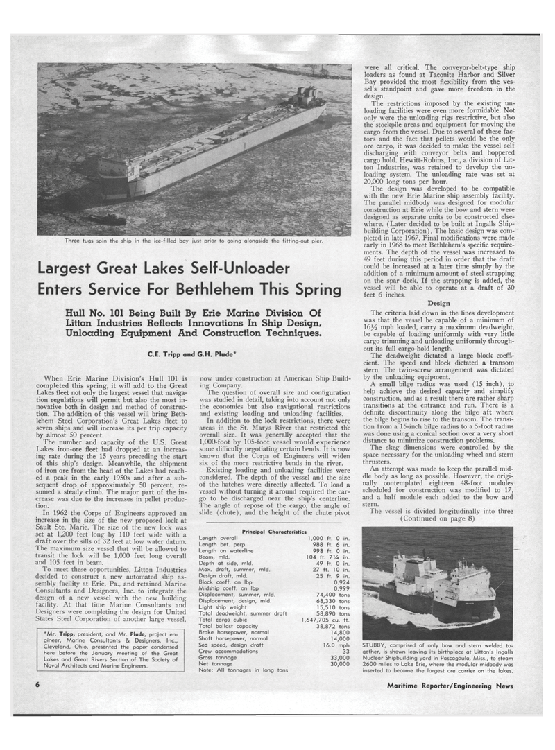
Three tugs spin the ship in the ice-filled bay just prior to going alongside the fitting-out pier.
Largest Great Lakes Self-Unloader
Enters Service For Bethlehem This Spring
Hull No. 101 Being Built By Erie Marine Division Of
Litton Industries Reflects Innovations In Ship Design,
Unloading Eguipment And Construction Techniques.
C.E. Tripp and G.H. Plude*
When Erie Marine Division's Hull 101 is completed this spring, it will add to the Great
Lakes fleet not only the largest vessel that naviga- tion regulations will permit but also the most in- novative both in design and method of construc- tion. The addition of this vessel will bring Beth- lehem Steel Corporation's Great Lakes fleet to seven ships and will increase its per trip capacity by almost 50 percent.
The number and capacity of the U.S. Great
Lakes iron-ore fleet had dropped at an increas- ing rate during the 15 years preceding the start of this ship's design. Meanwhile, the shipment of iron ore from the head of the Lakes had reach- ed a peak in the early 1950s and after a sub- sequent drop of approximately 50 percent, re- sumed a steady climb. The major part of the in- crease was due to the increases in pellet produc- tion.
In 1962 the Corps of Engineers approved an increase in the size of the new proposed lock at
Sault Ste. Marie. The size of the new lock was set at 1,200 feet long by 110 feet wide with a draft over the sills of 32 feet at low water datum.
The maximum size vessel that will be allowed to transit the lock will be 1,000 feet long overall and 105 feet in beam.
To meet these opportunities, Litton Industries decided to construct a new automated ship as- sembly facility at Erie, Pa., and retained Marine
Consultants and Designers, Inc. to integrate the design of a new vessel with the new building facility. At that time Marine Consultants and
Designers were completing the design for United
States Steel Corporation of another large vessel, *Mr. Tripp, president, and Mr. Plude, project en- gineer, Marine Consultants & Designers, Inc.,
Cleveland, Ohio, presented the paper condensed here before the January meeting of the Great
Lakes and Great Rivers Section of The Society of
Naval Architects and Marine Engineers. now under construction at American Ship Build- ing Company.
The question of overall size and configuration was studied in detail, taking into account not only the economics but also navigational restrictions and existing loading and unloading facilities.
In addition to the lock restrictions, there were areas in the St. Marys River that restricted the overall size. It was generally accepted that the 1,000-foot by 105-foot vessel would experience some difficulty negotiating certain bends. It is now known that the Corps of Engineers will widen six of the more restrictive bends in the river.
Existing loading and unloading facilities were considered. The depth of the vessel and the size of the hatches were directly affected. To load a vessel without turning it around required the car- go to be discharged near the ship's centerline.
The angle of repose of the cargo, the angle of slide (chute), and the height of the chute pivot
Principal Characteristics
Length overall 1,000 ft. 0 in.
Length bet. perp. 988 ft. 6 in.
Length on waterline 998 ft. 0 in.
Beam, mid. 104 ft. 7Va in.
Depth at side, mid. 49 ft. 0 in.
Max. draft, summer, mid. 27 ft. 10 in.
Design draft, mid. 25 ft. 9 in.
Block coeff. on Ibp 0.924
Midship coeff. on Ibp 0.999
Displacement, summer, mid. 74,400 tons
Displacement, design, mid. 68,330 tons
Light ship weight 15,510 tons
Total deadweight, summer draft 58,890 tons
Total cargo cubic 1,647,705 cu. ft.
Total ballast capacity 38,872 tons
Brake horsepower, normal 14,800
Shaft horsepower, normal 14,000
Sea speed, design draft 16.0 mph
Crew accommodations 33
Gross tonnage 33,000
Net tonnage 30,000
Note: All tonnages in long tons were all critical. The conveyor-belt-type ship loaders as found at Taconite Harbor and Silver
Bay provided the most flexibility from the ves- sel's standpoint and gave more freedom in the design.
The restrictions imposed by the existing un- loading facilities were even more formidable. Not only were the unloading rigs restrictive, but also the stockpile areas and equipment for moving the cargo from the vessel. Due to several of these fac- tors and the fact that pellets would be the only ore cargo, it was decided to make the vessel self discharging with conveyor belts and hoppered cargo hold. Hewitt-Robins, Inc., a division of Lit- ton Industries, was retained to develop the un- loading system. The unloading rate was set at 20,000 long tons per hour.
The design was developed to be compatible with the new Erie Marine ship assembly facility.
The parallel midbody was designed for modular construction at Erie while the bow and stern were designed as separate units to be constructed else- where. (Later decided to be built at Ingalls Ship- building Corporation). The basic design was com- pleted in late 1967. Final modifications were made early in 1968 to meet Bethlehem's specific require- ments. The depth of the vessel was increased to 49 feet during this period in order that the draft could be increased at a later time simply by the addition of a minimum amount of steel strapping on the spar deck. If the strapping is added, the vessel will be able to operate at a draft of 30 feet 6 inches.
Design
The criteria laid down in the lines development was that the vessel be capable of a minimum of 16Yi mph loaded, carry a maximum deadweight, be capable of loading uniformly with very little cargo trimming and unloading uniformly through- out its full cargo-hold length.
The deadweight dictated a large block coeffi- cient. The speed and block dictated a transom stern. The twin-screw arrangement was dictated by the unloading equipment.
A small bilge radius was used (15 inch), to help achieve the desired capacity and simplify construction, and as a result there are rather sharp transitions at the entrance and run. There is a definite discontinuity along the bilge aft where the bilge begins to rise to the transom. The transi- tion from a 15-inch bilge radius to a 5-foot radius was done using a conical section ove-r a very short distance to minimize construction problems.
The skeg dimensions were controlled by the space necessary for the unloading wheel and stern thrusters.
An attempt was made to keep the parallel mid- dle body as long as possible. However, the origi- nally contemplated eighteen 48-foot modules scheduled for construction was modified to 17, and a half module each added to the bow and stern.
The vessel is divided longitudinally into three (Continued on page 8)
STUBBY, comprised of only bow and stern welded to- gether, is shown leaving its birthplace at Litton's Ingalls
Nuclear Shipbuilding yard in Pascagoula, Miss., to steam 2600 miles to Lake Erie, where the modular midbody was inserted to become the largest ore carrier on the lakes. 6 Maritime Reporter/Engineering News
