Page 7: of Maritime Reporter Magazine (May 1971)
Read this page in Pdf, Flash or Html5 edition of May 1971 Maritime Reporter Magazine
 6
6
 8
8
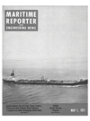
Philip Wallach
Philip Wallach, president of Colt Industries'
Power Systems Division in Beloit, Wis., commenting on the delivery of the MV Fal- con Lady stated: "We're proud to have en- gineered and furnished the prime movers for the first application of a diesel propul- sion system in a U.S.-flag commercial vessel of this size and horsepower. The Falcon
Lady brings the growing trend toward die- sel propulsion systems in the world's mari- time operations to the U.S. merchant fleet.
This trend is stimulated by lower initial cost of the equipment and lower operating costs." In discussing the Pielstick engines
Mr. Wallach continued, "We spent many months investigating engines and engine builders around the world before we agreed to be the licensee for this diesel power unit.
We selected the Pielstick because of its out- standing experience record and the avail- ability of a worldwide service organization.
On a worldwide basis, it is the most widely used, medium-speed, high-horsepower en- gine with over 1,100 sold." In conclusion he stated, "We are now manufacturing the
Pielstick engine and can offer the marine market the most complete horsepower range of any American diesel-engine manufac- turer."
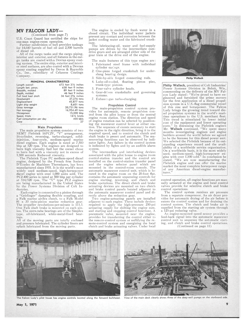
The Falcon Lady's pilot house has engine controls located along the forward bulkhead. View of the main deck clearly shows three of the deep-well pumps on the starboard side.
May 1, 1971 9
MV FALCON LADY— (Continued from page 7)
U.S. Coast Guard has certified the ships for one-man engine-room operation.
Further subdivision of hull provides tankage for 14,640 barrels of fuel oil and 2,500 barrels of diesel oil.
All of the cargo tanks and the cargo piping, interior and exterior, and all fixtures in the car- go tanks are coated with a Devran epoxy coat- ing system. The entire ship, exterior and interi- or steel surfaces, are also coated with a Devran epoxy coating supplied by Devoe & Raynolds
Co., Inc., subsidiary of Celanese Coatings
Company.
PRINCIPAL CHARACTERISTICS
Length overall 672 feet 3Vi inches
Length bet. perps. 638 feet 0 inches
Breadth, molded 89 feet 0 inches
Depth, molded 46 feet 9 inches
Full load keel draft 36 feet 2% inches
Deadweight 37,276 tons
Displacement 45,877 tons
Light ship weight 8,601 tons
Gross tonnage 20,751.96 tons
Net tonnage 16,954.49 tons
Horsepower 15,000 bhp
Speed, trials 1 6Vi knots
Fuel consumption per day 400 bbls
Crew 27
Main Propulsion
The main propulsion system consists of two
SEMT Pielstick 16PC2V, "V" arrangement, 16-cylinder, reversing, turbo-charged, solid- injection, four-cycle, medium-speed marine diesel engines. Each engine is rated at 7,500 bhp at 520 rpm. The engines are designed to burn high viscosity fuel but the owner chose to burn fuel with a viscosity not in excess of 1,500 seconds Redwood viscosity.
The Pielstick Type PC medium-speed diesel engine, designed by the French firm Societe
D'Etudes de Machines Thermiques, has been manufactured since 1951. It is the world's most widely used medium-speed, high-horsepower diesel engine with over 1,000 units sold. The
PC2-400 series is rated at 500 bhp per cylinder at 514/520 rpm. The "V" type PC2 engines are being manufactured in the United States by the Power Systems Division of Colt In- dustries.
Each engine is connected to a pinion through a "Geislinger" damping flexible coupling, and a Falk marine airflex clutch, to a Falk Model 81 x 33 twin-pinion marine reduction gear.
The propeller revolutions-per-minute is 111.3.
One Falk shaft brake is mounted on each pin- ion. The stern-tube bearings are of the Simplex type, oil-lubricated, white-metal-lined bear- ings.
All of the moving parts are totally enclosed and pressure lubricated. The cylinder liners are splash lubricated from the moving parts.
The engine is cooled by fresh water in a closed circuit. The individual water jackets prevent any contact and corrosion between the jacket cooling water and the fabricated crank- case.
The lubricating-oil, water and fuel-supply pumps are driven by the intermediate cam- drive gears and are arranged either side of the gear train at the drive end of the engine.
The main features of this type engine are: 1. Fabricated steel frame with individual cylinder casings. 2. One-piece forged crankshaft for under- slung bearing design. 3. Side-by-side forged connecting rods. 4. Lube-oil-cooled, floating piston pins, trunk-type pistons. 5. Four-valve cylinder heads. 6. Gear-driven crankshafts and governing systems. 7. Exhaust-gas turbo-charging.
Propulsion Control
The main-propulsion control system pro- vides for automatic, remote propulsion con- trol from the pilot house or from the central engine room station. The direction and speed of engine rotation can be selected by position- ing the maneuver control lever at either sta- tion. The sequence of events necessary to start the engine in the right direction, bring it to the required speed, and to control the clutch and shaft brake is preset and automatic. The ma- neuvering functions can be observed by indi- cator lights. Any failure in the control system is indicated by lights and by an audible alarm system.
The intermediate and interlocking devices associated with the pilot house to engine room control-station transfer and the control are installed on the control-station transfer panel and the engine selector panel which are mounted in the control-room console. The automatic maneuver control unit, which is lo- cated in the engine room on the 20-foot flat, contains the automatic sequencing controls for engine starting, reversing, and clutch and brake operations. The direct clutch and brake actuating devices are mounted on two clutch and brake control panels located adjacent to the automatic maneuver control panel and di- rectly above the reduction gear.
Two engine-actuating panels are installed adjacent to each engine. These include devices required to apply the high-pressure 250-psi actuating supply for shifting the engine cam, and starting and stopping control functions. A pneumatic valve, mounted near the engine, provides for transferring the control either to the remote-control system or nullifying the re- mote-control system and energizing the local clutch and brake actuating valves. Under local control operation, all engine functions are man- ually actuated at the engine and local control valves provide for selective clutch and brake control operations.
The control system receives air pressure from a separate compressor. An air dryer pro- vides for automatic drying of the air before it enters the control system and for draining the control system. The clutch and brake air is supplied from the starting air system through a 125-psi reducing valve.
An engine-mounted speed sensor provides a feed-back signal into the automatic maneuver control unit to sequence the automatic start- ing, and clutch and brake control operations. (Continued on page 11)
