Page 9: of Maritime Reporter Magazine (June 1971)
Read this page in Pdf, Flash or Html5 edition of June 1971 Maritime Reporter Magazine
GTS Euroliner (Continued from page 9) associated with a single input shaft, have hardened and ground high-speed pinions. In addition, an AEG 1,000- kw shaft-driven alternator is connect- ed to each of the two reduction gears and equipped with a series connected thyristor-type inverter to supply ship's electrical power.
The main propulsion-control sys- tem was designed and built in a co- ordinated effort by TP&MS and
AEG-Schiffbau, Germany. Unattend- ed engine room operation was a fixed requirement with bridge control as well as bridge wing controls for maneuvering. A fully automated monitor system makes possible a 16 hour, unsupervised operation with remote control from the bridge.
The speed of the propeller shaft is set for "ahead" as well as "astern" operation by means of the control lever. The adjustment of the pro- peller pitch is also combined with this single control lever for each shaft.
The automatic starting system brings the fuel and lubricating oil systems, the propulsion-unit cooling system and the seawater circulating system into operation. As soon as the gas turbine is cleared for opera- tion, it is started by means of a push- button on the engine control panel.
The engine can also be started manually whereby all auxiliary ma- chines are started separately through pushbuttons. A mode selector switch with five positions ensures the func- tionally correct order of the manual starting procedure.
After reaching idling speed, the gas turbine is accelerated and the propeller pitch is adjusted through operating the control lever either on the bridge or on the engine control panel. Above the maneuvering speed, the propeller is operated with maxi- mum pitch.
When reversing, the control lever is set to the required astern speed.
The gas turbine is brought to the minimum permissible power. As soon as the shaft speed is low enough to avoid the so called "windmill effect," the propeller moves into the set pitch for astern operation.
The machine is stopped under nor- mal conditions by means of operating a pushbutton on the engine control panel. The idling speed is main- tained for a short time in order to cool the unit before it comes to a standstill.
During the design work for the control system, it was necessary to investigate the operation of the shaft generator during all maneuvering conditions. As the generator cannot be loaded under a certain minimum speed, this minimum speed during maneuvers had to be fixed. During maneuvering operations in the "ahead" or "astern" direction of the ship, the speed of the propeller shaft is held constant and the ship's speed is altered through adjusting the pitch of the propeller. Above maneuvering speed, the propeller pitch remains constant and the generator speed al- ters relative to the shaft speed. The whole speed range from "dead slow" to maneuvering speed "full ahead" is therefore covered with a constant speed of the turbine of 2,000 rpm while the pitch of the propeller is automatically altered. With a ma- chine output of 2 X 5,000 shp and maximum propeller pitch, the ship attains a speed of about 16 knots.
From this output up to the full out- put of 2 X 26,000 shp, the propeller pitch is 100 percent. In order to at- tain the maximum output of 30,000 shp, a mechanical block on the control lever of the engine telegraph must be freed.
The automatic propulsion controls are monitored by a superimposed
AEG data-processing unit of the "Datazent 100" system. It should be noted that, for this equipment, the (Continued on page 12)
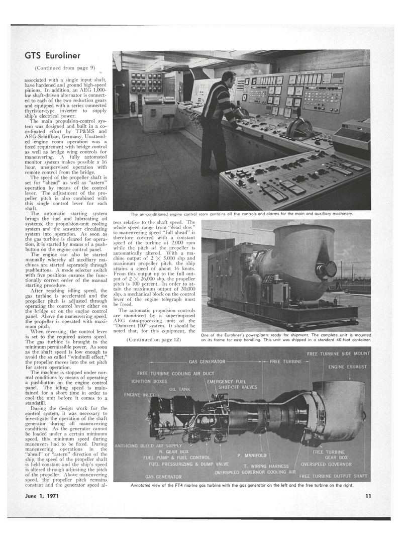
One of the Euroliner's powerplants ready for shipment. The complete unit is mounted on its frame for easy handling. This unit was shipped in a standard 40-foot container.
The air-conditioned engine control room contains all the controls and alarms for the main and auxiliary machinery
Annotated view of the FT4 marine gas turbine with the gas generator on the left and the free turbine on the right.
June 1, 1971 11

 8
8

 10
10
