
Page 16: of Maritime Reporter Magazine (September 1971)
Read this page in Pdf, Flash or Html5 edition of September 1971 Maritime Reporter Magazine
 15
15
 17
17
Turbopitch Propulsion— (Continued from page 16)
Reduction Gear
To take advantage of the weight and space savings possible with a lightweight gas turbine, traditional reduction-gear arrangements, de- signs and manufacture were dis- carded in favor of an advanced, lightweight and compact design.
The 'basic goal was to develop a unitized reduction gear / prime mover/propeller assembly with the simplest possible engine mounting and foundation. To this end, the gas turbine was cantilevered off the input side of the reduction gear, and the oil-distribution box for the
CRP propeller integrated with the output shaft assembly. The output shaft bearings were sized to take full propeller thrust, which is trans- mitted to the hull via the gear- box mounting. This arrangement achieved several significant results : 1. Gas turbine to gear box align- ment problems are non-existent. A double engagement gear-type cou- pling on the input shaft accommo- dates any slight misalignment. 2. No engine foundation is re- quired. 3. No separate propeller thrust bearings are required, nor thrust- bearing supports. 4. The CRP oil-distribution box may he mounted forward of the re- duction gear, eliminating large- diameter high-pressure oil seals.
The hollow bore of the gear ac- commodates the oil tubes leading to the CRP huh. 5. Accessory drives, such as for the CRP oil pumps, are taken off the reduction gear.
The reduction gear is the Phila- delphia Gear Model 13 VMGHS with Model CQ 33 clutch and brake.
The reduction gear is a helical, double-reduction unit, using hard- ened and ground gearing through- out. Anti-friction bearings are used except on the high-speed input shaft, which uses sleeve bearings and a pivoted shoe-type thrust bearing. The housing is of light- weight welded-steel construction, stress relieved after welding. The housing is split at each shaft cen- terline. The splits are ground and sealed without the benefit of gas- kets 'by virtue of the smooth finish.
An even lighter weight housing of welded aluminum was considered.
However, the potential weight savings was not sufficient to war- rant the higher material and manu- facturing costs.
The essential reduction-gear characteristics are given in Table 1.
Table 1—Reduction Gear Data
Basic rating
Service factor
Input speed
Output speed
Gear ratio
Int. shaft speed
Clutch shaft speed
Design life-bearings
Lube pump
Oil sump
Gear blanks
Shaft material
High-speed shaft brgs.
High-speed thrust brg.
Low-speed brgs.
Int. shaft brgs.
Propeller thrust
The basic reason for the sizeable weight and bulk reduction is the adoption of hardened and ground, single-helical gearing. The helix angles for the gears range from 11 to 12 degrees. These angles result in low hearing thrust loads, which in turn permit all but the high- speed gears to he straddle mounted
CLUTCH -BRAKE
THRUST BEARING
H.S. GEARS / RSL EEVEBRQ.
JL /b——^a in P
COUPLING
INTERMEDIATE 3 HAFT
CE3 s ANTIFRICTION B
LOW SPEED SHAFT* 4
PROPELLER THRUST BEARING
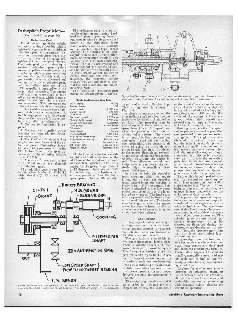
Figure 2—The servo control box is mounted on the reduction gear box. Shown in this view are: 1-yoke, 2-oil tube, 3-control handle, 4-drain, and 5-shaft extension. 1,250 hp 1.50 1 8,500 rpm 885 rpm 20.90 3,628 rpm 3,628 rpm 20,000 hr.
Motor driven
Integral
Forged
Alloy steel
Sleeve type
Pivoted shoe
Tapered roller
Tapered roller
Tapered roller
US. SEARS
Figure 3—Schematic arrangement of the reduction gear, which incorporates in the assembly the clutch, brake and thrust bearings. The total dry weight is 1,915 pounds. on pairs of tapered roller bearings.
This arrangement is shown in
Figure 3.
A clutch is incorporated on the intermediate shaft to allow the gas turbine to he idled and started at no load. The propeller can be picked up with the clutch at any speed from idle to full speed, and with the propeller pitch neutral or any other setting. The clutch is of multiple-disc construction, and uses forced oil for cooling and lubrication. The clutch is air operated, using the ship's air sup- ply at 85 psi. The air is introduced to the piston through an external rotary union which may be serviced without disturbing the clutch it- self. The oil-cooled clutch and brake were chosen due to the rela- tively high intermediate shaft speed (3,628 rpm).
In order to keep the propeller from creeping with the engine idling, and to keep the propeller from back-driving the turbine, a brake is built into the clutch. This brake is attached to the low-speed pinion, and grounds it to the hous- ing when engaged. The brake also is air operated and is interlocked with the clutch controls. The brake may be engaged when the engine speed has been reduced to idle, or approximately 10 seconds after the clutch has been released.
Gas Turbine
In high-speed craft where weight is important and in work boats where precise control is required, the selection of a gas turbine as the driver seems natural.
The gas turbine is available in two basic mechanical forms, fixed wheel or constant speed and free- power turbine or variable speed.
The free-power turbine gives the greatest versatility to the CRP sys- tem in terms of control, adaptation to various craft and performance.
Free-power turbine powerplants al- so differ from other engines in that their power production and power delivery systems are mechanically separated.
The series of gas turbines—1,000 hp to 2,500 hp—selected for this project all employ the same basic sections and all are about the same size and weight: 36 inches high, 36 inches wide and 48 inches long and weighing about 1,100 pounds. Be- cause of the design of these en- gines, output shaft speeds are naturally quite high, in the order of 15 to 17 thousand rpm.
Gearing to cope with this speed and to produce a useable propeller rpm provided a unique mounting arrangement. The engine was can- tilevered directly from the gear, us- ing the inlet housing flange as a mounting ring. This engine mount- ing makes change-out a simple job and alignment checking no longer a requirement. The turbine acces- sory gear provides the mounting pads for the starter, 'fuel control, governor and assorted drives for up to five separate items, such as lube pumps for external equipment, generators, hydraulic pumps, etc.
Each engine is equipped with an electrical control system complete with instrumentation and solid- state control box. The control box includes replaceable modules, se- quence failure diagnostic devices and a service data recorder.
The power-management request for a change in power or torque is translated to the engine as a vari- ation in fuel flow. The maximum rate of this flow is normally present as a function of ambient tempera- ture and compressor pressure. This scheduling to prevent either ex- cessive temperature during in- creases, or flame-out during de- creases, over-rides the control mo- tion. Thus, the operator may slam the throttle or speed-select lever without concern.
Lightweight gas turbines suit- able for marine use have been de- rived from extensively developed and produced aircraft gas turbines.
These latter engines are conven- tionally, manually started and uti- lize wide-cut jet fuel of low vis- cosity suitable for very cold operat- ing conditions.
Engines for marine use have a different optimization, including use of heavier fuels for economy, elimination of smoke and odor, and preferably automatic sequencing with integral safety circuits for simplified operation. 18 Maritime Reporter/Engineering News
