Page 6: of Maritime Reporter Magazine (September 1971)
Read this page in Pdf, Flash or Html5 edition of September 1971 Maritime Reporter Magazine
 5
5
 7
7
The USNS Hayes— (Continued from page 6)
Hull Construction
The hull form, which is identical to that of the Navy's ASR ships but slightly smaller was developed after extensive model tests.
When viewed from the bow, the two hulls appear as if a conventional hull was split longi- tudinally and then separated. When viewed from the stern, each hull is conventionally sym- metrical about a buttock plane. Therefore, each hull by itself is not transversely stable and there is no parallel middle 'body.
Because of this design feature, Todd Ship- yards decided to use a modular technique for construction. A total of 55 modules were de- lineated, 27 of which are below the main deck.
The start of construction of each was se- quenced. The first modules incorporated the machinery spaces and were followed in order by the midships sections, the immediate bridg- ing cross structure, and thence simultaneously forward and aft on both hulls and thereafter upwards.
The twin hulls are ice strengthened and transversely framed. The cross structure is de- signed to withstand the maximum load cre- ated by the ship being supported on one bow and the opposite stern. To carry these loads, there are six massive "I" beams running across the ship. They are about 21 feet deep and form part of the transverse bulkheads.
PRINCIPAL CHARACTERISTICS
Length overall 246 ft. 5 in.
Length bet. perps. 220 ft. 0 in.
Beam, maximum 75 ft. 0 in.
Beam, each hull 24 ft. 0 in.
Distance bet. hulls 7 ft. 0 in.
Depth, amidships 34 ft. 0 in.
Draft, full load 17 ft. 9 in.
Draft, navigational 21 ft. 3 in.
Displacement, light 2,329 tons
Displacement, full load 2,876 tons
Design full power 5,400 bhp
Aux. propulsion power 330 bhp
Shaft rpm, full power 1 39
Sustained sea speed 5 knots
Creep speed 2-4 knots
Ship's Complement
Officers 1 1
Crew 33
Scientists 0
Machinery
The main propulsion plant consists of two (one in each hull) geared diesel engines fur- nished by the Electromotive Division of Gen- eral Motors Corporation. The engines, Model 20-645E5, drive Lips/Ampower CRP 12-foot diameter propellers through Western Gear
Corporation, Model 840 MGDP-180, reduction gears and 10-inch diameter shafting. The shaft- ing is supported by Waukesha line-shaft bear- ings and have face-type shaft seals furnished by the Syntron Division of the FMC Corpora- tion. The B.F. Goodrich Company furnished cutless rubber stern-tube bearings.
Besides the main propulsion engines which develop 2,700 bhp each, there are two auxiliary propulsion units for quiet operations which develop 165 bhp each. These units were sup- plied by Stewart & Stevenson, Inc. While the main units provide a sustained speed of 15 knots, the auxiliary units provide a sustained speed of two to four knots. These units are connected to the reduction gear by clutches.
At slow speeds, the ship is able to turn in approximately its own length by reversing the pitch of one of the CRP propellers.
The ship's-service electrical plant consists of three 350-kw, 450-volt, 3 phase, 60-cycle Cater- pillar diesel-generator sets. Two 75-kw gener- ators, furnished by Western Branch Diesel
Corporation, Model 4045N, provide for scien- tific and essential services equipment. They are located on the 03 level and are resiliently mounted to reduce the ship's noise during 8
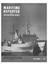
All quarters are comfortably outfitted, as shown by the above view of the first mate's stateroom. His berth in this room is a single, twin-size bunk. All quarters are fitted with a recirculating air-conditioning "system. silent derations. One similar 75-kw diesel- generator is provided for emergency use.
A General Electric Company centralized machinery-control system is provided to re- duce manning requirements. The central con- trol system provides for an engineering opera- tion station (EOS), containing switchboards for the ship's service and scientific generators and for electric-power distribution, essential- lighting load center, the main control console, an alarm and data logger, bell logger, and nu- merous other machinery and valve remote con- trols, alarms, system status displays and in- dicators.
The EOS is designed for one licensed watch stander and completely unmanned machinery spaces. It is located on the main deck, astride the cross structure in the aftermost space of the forward deckhouse. Although it has rela- tively direct access to both machinery spaces, it does not have visual access. On the main control console, equipment is provided for remote selection, starting, speed control, and stopping of the propulsion engines. Provision is made in the EOS for remote starting, paral- leling and stopping of generators, and for re- mote transfer of tankage among the other engi- neering functions that are also included.
The machinery-control console system pro- vides for remote control of the propulsion ma- chinery for ship speed and direction from the ship control consoles in the pilot house, both bridge wings and the auxiliary ship control sta- tion located aft. For ship speed, these controls and a similar control on the main console in the EOS are single-lever, programmed for automatic matching of propeller pitch and rpm relationships. Heretofore, such coordination was achieved with mechanical cams whereas in
T-AGOR-16 electronic logic circuits, designed by General Electric, establish the control pro- grams. This automatic control is supplemented by remote-operated manual controls on the
EOS main console for the separate control of propeller pitch and/or rpm which the engineer can use to make special adjustments for endur- ance runs.
The pilot house control can override the bridge wings and the auxiliary control station.
Similarly, the EOS can override the pilot house. Further, the EOS can permissively transfer manual control to a local operating station at each main and auxiliary propulsion- engine complex. Features are incorporated so that transfer of control in the automatic mode can be made without change in the pitch/rpm settings.
The monitoring and display of machinery- plant management information is accomplished in a General Electric data center which is rela- tively new for shipboard application. This cen- ter, located contiguous with the EOS main control console, monitors remote machinery performance. The most important operating data is displayed continuously, for example, propeller rpm and pitch, diesel cooling water and combined cylinder exhaust temperatures,
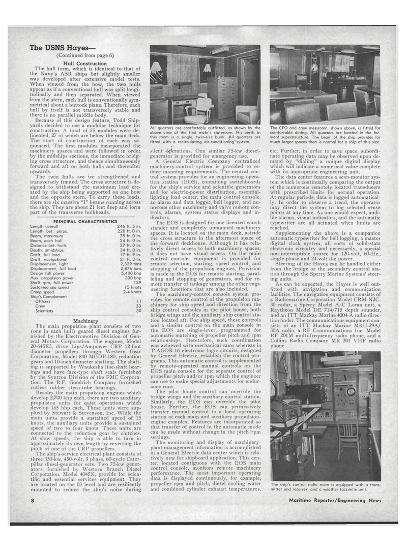
The CPO and crew messroom, shown above, is fitted for comfortable dining. All quarters are located in the for- ward superstructure. The beam of the ship provides for much larger spaces than is normal for a ship of this size. etc. Further, in order to save space, subordi- nate operating data may be observed upon de- mand by "dialing" a unique digital display which will indicate a numerical value complete with its appropriate engineering unit.
The data center features a scan-monitor sys- tem which is continually comparing the output of the numerous remotely located transducers with prescribed limits for normal operation.
At regular periods, data is logged automatical- ly. In order to observe a trend, the operator may direct the system to log selected sense points at any time. As one would expect, audi- ble alarms, visual indicators, and the automatic typewriter are all actuated when limits are reached.
Supplementing the above is a companion automatic typewriter for bell logging, a master digital clock system, all sorts of solid-state electronic circuitry and necessarily, a special non-interruptible source for 120-volt, 60-Hz., single-phase and 24-volt d-c power.
Steering of the Hayes can be handled either from the bridge or the secondary control sta- tion through the Sperry Marine Systems' steer- ing units.
As can be expected, the Hayes is well out- fitted with navigation and communication facilities. The navigation equipment consists of a Radiomarine Corporation Model CRM-N2C- 30 radar, a Sperry Model A/C Loran unit, a
Raytheon Model DE 714/715 depth sounder, and an ITT Mackay Marine 4004-A radio direc- tion finder. The communications equipment con- sists of an ITT Mackay Marine MRU-29A/ 30A radio, a RF Communications Inc. Model
RF 201M multi-frequency radio phone, and a
Collins Radio Company MR 201 VHF radio phone.
The ship's control radio room is equipped with a trans- mitter and receiver, and a weather facsimile unit.
Maritime Reporter/Engineering News
