
Page 22: of Maritime Reporter Magazine (April 1972)
Read this page in Pdf, Flash or Html5 edition of April 1972 Maritime Reporter Magazine
 21
21
 23
23
Marine Turbine Gearing- (Continued from page 30) be moved from the main gear casing to the turbine baseplate to make the best use of the longer quill shaft which connects the first and second h-p gears.
The short quill shaft between the h-p turbine rotor and the first h-p sun wheel then only has to take care of deflections within the turbine base- plate.
Today, the AP gear family con- sists of a number of types with torque numbers (kW/rpm) equal to 90 to 420. For torque numbers over 180, all are triple-reduction gears.
With alloy steel in the bull wheel and
K factors in accordance with the rules of all classification societies, the AP design can cover 46,000 shp at 80 rpm with a bull wheel of about 210 inches in diameter. It is at present considered that this dimension should not be exceeded due to handling and transport problems. 1 \/ \ r
B ) ( b f^t) i
Figure 3—-Propeller arrangements for
VLCC ships studied by Kockums shipyard.
For containerships with propeller speeds of 115 to 130 rpm, a torque number of 420 gives powers of 70,000 up to 75,000 shp, which should be sufficient for the coming demand as far as can be estimated, having due regard to the cavitation problems of the propellers.
Gears For Very High Torques
Many shipyards are working on studies for the next generation of
VLCC and limits for single-shaft en- gines are being discussed. For the time being, propeller manufacture and the stern-tube bearings, rather than the gearing, have limited the shaft torques. According to the pro- peller designers, propellers for low speed can now be made up to 40- feet in diameter and of weights up to 70 tons, sufficient for 50,000 shp at 80 rpm, representing a torque number of 460, which might be some- what more than could be managed in practice by the largest triple-reduction
AP gear. The stern-tube bearing is already giving trouble in some cases with the largest propeller weights.
As the bearing pressure increases with size—weights increase with the cubic dimension while the bearing area only increases with the square of the linear dimension—the load- carrying oil film more or less disap- pears at propeller speeds lower than 15 to 20 rpm. With barring of the engines at propeller speeds below one rpm, there is definitely a risk of white metal wear in the stern-tube bearing unless jacking oil is applied.
The SKF design with a roller bear- ing, Figure 2, offers an interesting alternative. The roller bearing is short and cheap and can be inspected at sea. Fatigue tests prove that the bearing can work for quite long pe- riods even with a very high content of water in the lubricating oil.
For extremely high torques exceed- ing the present capacity of the AP series or any other two-pinion con- figuration, the locked train is a natu- ral choice. For torque numbers around and above 500 (e.g. corres- ponding to 55,000 shp at 80 rpm), and low propeller speeds an arrange- ment is proposed which employs triple-reduction gearing on the h-p side. For large powers the speed dif- ference, which is approaching a factor of 2.5 times between the h-p and 1-p turbine, has grown sufficiently large to justify a primary gear which contrib- utes to a balanced locked-train design.
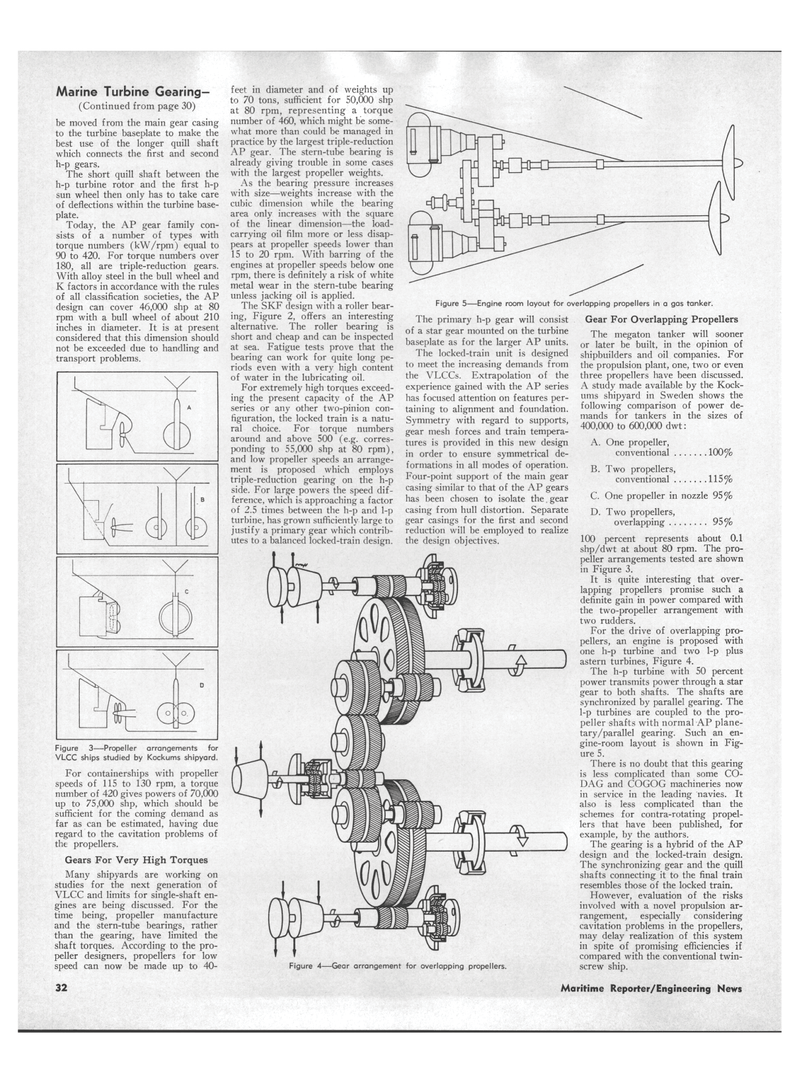
Figure 5—Engine room layout for overlapping propellers in a gas tanker.
The primary h-p gear will consist of a star gear mounted on the turbine baseplate as for the larger AP units.
The locked-train unit is designed to meet the increasing demands from the VLCCs. Extrapolation of the experience gained with the AP series has focused attention on features per- taining to alignment and foundation.
Symmetry with regard to supports, gear mesh forces and train tempera- tures is provided in this new design in order to ensure symmetrical de- formations in all modes of operation.
Four-point support of the main gear casing similar to that of the AP gears has been chosen to isolate the. gear casing from hull distortion. Separate gear casings for the first and second reduction will be employed to realize the design objectives.
Gear For Overlapping Propellers
The megaton tanker will sooner or later be built, in the opinion of shipbuilders and oil companies. For the propulsion plant, one, two or even three propellers have been discussed.
A study made available by the Kock- ums shipyard in Sweden shows the following comparison of power de- mands for tankers in the sizes of 400,000 to 600,000 dwt:
A. One propeller, conventional 100%
Figure 4—Gear arrangement for overlapping propellers.
B. Two propellers, conventional 115%
C. One propeller in nozzle 95%
D. Two propellers, overlapping 95% 100 percent represents about 0.1 shp/dwt at about 80 rpm. The pro- peller arrangements tested are shown in Figure 3.
It is quite interesting that over- lapping propellers promise such a definite gain in power compared with the two-propeller arrangement with two rudders.
For the drive of overlapping pro- pellers, an engine is proposed with one h-p turbine and two 1-p plus astern turbines, Figure 4.
The h-p turbine with 50 percent power transmits power through a star gear to both shafts. The shafts are synchronized by parallel gearing. The 1-p turbines are coupled to the pro- peller shafts with normal AP plane- tary/parallel gearing. Such an en- gine-room layout is shown in Fig- ure 5.
There is no doubt that this gearing is less complicated than some CO-
DAG and COGOG machineries now in service in the leading navies. It also is less complicated than the schemes for contra-rotating propel- lers that have been published, for example, by the authors.
The gearing is a hybrid of the AP design and the locked-train design.
The synchronizing gear and the quill shafts connecting it to the final train resembles those of the locked train.
However, evaluation of the risks involved with a novel propulsion ar- rangement, especially considering cavitation problems in the propellers, may delay realization of this system in spite of promising efficiencies if compared with the conventional twin- screw ship. 32 Maritime Reporter/Engineering News
