
Page 13: of Maritime Reporter Magazine (January 1973)
Read this page in Pdf, Flash or Html5 edition of January 1973 Maritime Reporter Magazine
 12
12
 14
14
Bridgestone Proposes
Flat Membrane LNG Tanks
Plane-Surface Dual Semi-Membrane LNG Tanks Combine The
Advantages Of The Membrane Tank And Pressure Vessel.
Katsuro Yamamoto*
The basic concept for a flait membrane-type
LNG tanker originated from experience gained by the Bridgestone Liquefied Gas Co., Ltd. in the construction of LPG and LEG tankers and shore tanks, under the firm's design.
The general concept of the system is shown in Figure 1. It consists of a dual-membrane tank, the inner semi-membrane being the pri- mary tank and the outer semi-membrane form- ing the secondary barrier. Sandwiched between the two membranes is a buffer layer of plywood panels. The primary tank and secondary bar- rier are composed of flat walls, cylindrical edges and ball corners, and are enclosed in a load-bearing insulation structure.
The only point of fixation of the dual-mem- brane tank to the supporting structure is at the dome part of the tank. The rigid dome is supported by the ship's deck structure. There are several variations possible in this system, depending on the size and shape of the ship hold, i.e., the thickness of the membranes, radi- us of the cylinders and balls, type of load- bearing insulation structure, and the fabrica- tion method of the tank.
As shown in Figure 2, if a primary tank is fabricated of 9% Ni steel plate to the same size at ambient temperature as that of the in- side surface of the supporting structure and is enclosed in and supported by a load-bearing insulation structure, and when loaded with liquid at the same temperature, then all plane walls and bottom cylinders (hereinafter refer- red to as leaning parts) are kept in firm con- tact with the surface of the load-bearing in- *Mr. Yamamoto, senior managing director, Bridge- stone Liquefied Gas Co. Ltd., Tokyo, Japan, presented the paper condensed here before the recent Third
International Conference and Exhibition on Liquefied
Natural Gas in Washington, D.C. sulation structure through the plywood buffer and the secondary barrier.
However, all vertical cylinders, top cylin- ders, and ball corners (hereinafter referred to as free parts) are freely self standing because of different radii of the primary tank, plywood buffer and secondary barrier.
When the above tank, which is sized at normal temperature, is cooled to a low temper- ature, it will shrink and a clearance will take place between the tank and the load-bearing insulation. If this tank is now containing a liquid at a low temperature, then the pressure of the load will distend the plane surface sides until they contact the rigid load-bearing in- sulation. Consequently, the free parts and the areas of the plane surface near the free parts will be subjected to bending stress as well as the normal hoop tension. Due to the fact that excess bending stress in the membrane will cause a fatigue fracture, it is most desirable to eliminate this stress.
Therefore, the primary tank is to be con- structed to an over-size which is equal to the amount of thermal contraction. In this way, the thermal contraction brings the primary tank to right size at the cargo temperature' and under these circumstances, the tank isi subjected only to hoop tension. Thus, in this system it is possible to give known stress de- sign to the primary tank, the order of which can be made to be far below the allowable stress limit of the material used. From this fact, it can be readily understood that the de- sign has similar characteristics to the pressure vessel, requiring no secondary barrier.
The secondary barrier of 3-mm stainless steel is also fabricated to oversize, the shape being similar to that of the primary tank. Un- der loaded conditions, the leaning parts trans- mit cargo load to the supporting structure, but the free parts of the secondary barrier are in no way affected by the cargo load. For this reason, the secondary barrier is not subjected to hoop stress under cargo condition.
It may not be necessary to have the plywood buffer sandwiched between the primary tank and the secondary barrier. But in order to maintain a better autonomy of the primary tank and secondary barrier, a 20-mm thick continuous plywood sheet having 2-m radius in the free parts is sandwiched between them.
This plywood buffer provides a protection to the primary tank and the secondary barrier against possible damage. It also prevents the primary tank and secondary barrier from in- terfering with each other.
In general, any insulation structure can be accepted, should it be designed to support the cargo load and to provide the insulation effect, and also it can be closely related to the fabrica- tion methods of the tank.
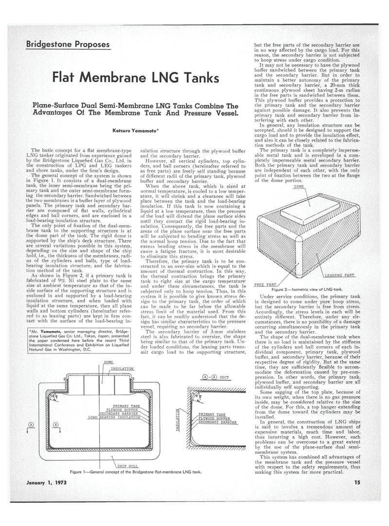
The primary tank is a completely imperme- able metal tank and is enveloped in a com- pletely impermeable metal secondary barrier.
Both the primary tank and secondary barrier are independent of each other, with the only point of fixation between the two at the flange of the dome portion.
DOME
Under service conditions, the primary tank is designed to come under pure hoop stress, but the secondary barrier is free from stress.
Accordingly, the stress levels in each will be entirely different. Therefore, under any cir- cumstances, there is no possibility of a damage occurring simultaneously in the primary tank and the secondary barrier.
The shape of the dual-membrane tank when there is no load is maintained by the stiffness of the cylinders and ball corners of each in- dividual component, primary tank, plywood buffer, and secondary barrier, because of their respective degree of rigidity. But at the same time, they are sufficiently flexible to accom- modate the deformation caused by pre-com- pression. In other words, the primary tank, plywood buffer, and secondary barrier are all individually self supporting.
Some sagging of the top plate, because of its own weight, when there is no gas pressure inside, may be considered relative to the size of the dome. For this, a top hanger extending from the dome toward the cylinders may be installed.
In general, the construction of LNG ships is said to involve a tremendous amount of expensive materials, much time and labor, thus incurring a high cost. However, such problems can be overcome to a great extent by the use of the plane-surface dual semi- membrane system.
This system has combined all advantages of the membrane tank and the pressure vessel with respect to the safety requirements, thus making this system far more practical.
DOME
January 1, 1973 15
