Page 9: of Maritime Reporter Magazine (November 1973)
Read this page in Pdf, Flash or Html5 edition of November 1973 Maritime Reporter Magazine
 8
8
 10
10
Bethlehem Beaumont Delivers The Pacesetter I - (Continued from page 9)
Drawworks
Prime Movers
Mud Pumps
Rotary Table
Derrick
Drilling Equipment
National 1625-DE powered by two GE 752 motors.
Four-EMD 16E8-GW6-1400 KW 1950 HP.
Two-National 12P-160 powered by two GE 752 motors.
National C375 Z7Vi powered by GE 752 R Motor.
Lee C. Moore, 1,000,000 Lb. static load capacity.
Overall length
Beam, overall
Height, keel to top of main deck
Lower hulls
Beam
Length of hulls
Depth of hulls
Caissons (6)
Diameter
Elevation of top above keel
Quarters accommodations
Draft (towing)
Draft (normal drilling)
Draft (severe storm)
Displacement (towing)
Displacement (normal drilling)
Displacement (severe storm)
Variable deck load
Certification: ABS ond U.S. Coast Guard with no restrictions 260 feet 200 feet 1 11 feet 50 feet 260 feet 20 feet 32 feet 1 1 1 feet 80 17 feet 60 feet 45 feet 10,500 L.T. 19,288 L.T. 17,080 L.T. 2,000 L.T. with its 6,000-shp propulsion plant to travel independently at speeds well over eight knots.
In each hull, four DC motors drive a 10-foot-diameter propeller in a Kort nozzle through a reduc- tion gear and normal marine shaft installation, with 3,000 shp per side, 6,000 shp total. The Kort noz- zles provide increased thrust and speed, reduce propeller racing in heavy seas and provide better ma- neuverability at the drilling loca- tion.
The designers took a unique step in deciding not to fit rudders, but instead to steer and maneuver with the two wide-spa'ced propellers.
Course keeping is maintained through a rate control gyro and gyropilot, and steering is accom- plished by fine differential rpm con- trol. Sea trials confirmed superb steering and handling qualities without the expense of 'fitting rud- ders and steering gears, nor their subsequent maintenance over the years.
Structure. The unit meets all re- quirements of the American Bu- reau of Shipping and is classed as an A-l M Column stabilized barge with an unrestricted load line. Safe- ty equipment has unrestricted cer- tification from the U.S. Coast
Guard and the Norwegian Mari- time Directorate.
The structure utilizes ABS grades of ship steel with bracings, girders and vital connections of low alloy high-strength steel. EH grade steel (low temperature, notch tough) is used at all vital joints of bracings, deck girders and caisson connections, A total of 6,000 long tons of steel was used in the con- struction of Pacesetter I.
Substructure. A Lee C. Moore unit, 33 feet high, 40-foot by 39- foot 3-inch base, and 40-foot by 51- foot 6-inch rig floor. The spider deck is 65 feet 9 inches by 40 feet, allowing for the operation of dou- ble B.O.P. stacks, 30 feet high and weighing 85 tons each. The opera- tion is conducted by two Lee C.
Moore track-mounted 80-ton bridge cranes provided with two B.O.P. dollies powered by electric motors.
Mooring System. The Pacesetter
I has eight anchor lines, each con- sisting of 3,000 feet of 3-inch chain connected to a 30,000-pound Baldt anchor with pendant lines and mooring buoys. The unit has four
National D 503E double wildcat windlasses with fairleaders located on each corner caisson with a tubu- lar pipe structure for housing each anchor.
Tension Equipment. Four Ruck- er 60,000-pound riser tensioners and four Rucker guide line tensioners.
Cranes. Two National cranes, one with 80-foot boom and 86-ton ca- pacity and one with 120-foot boom with 60-ton capacity, plus one
Manitowac crane with 110-foot boom and 38-ton capacity.
Variable Load. The Pacesetter I carries 2,000 long tons of variable load topside, giving a clearance above the still water line of 51 feet under normal drilling conditions.
The clearance is easily increased in the event of storm conditions.
Storage Onboard. Bulk mud and cement, six 1,500-cubic-foot tanks; sack mud and cement, 6,000 sacks; fuel, 6,882 barrels; drill water, 12,- 245 barrels; potable water, 1,322 barrels and two watermakers, and liquid mud, 7,600 cubic feet.
In summary, the Western Com- pany of North America's new Pace- setter drilling units will have su- perior speed, excellent stability, above average maneuverability on location, high-capacity drilling equipment, high deck load capacity, rugged eight-point chain mooring system and ability for unrestricted travel anywhere in the world.
Principal Characteristics
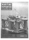
Central control panel of Pacesetter I, located adjacent to pilothouse, employs so- phisticated instrumentation to monitor operation of the drilling unit. The console shown controls all pumping of hull tanks, with continuous registering of the amount of fluid in each tank visible on the circular gauges seen at the top of the picture.
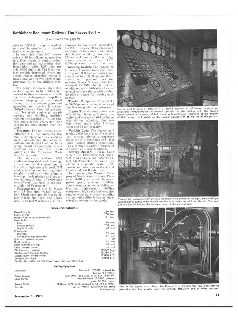
View of the mud pump room showing the triplex mud pumps on the right, the centrifugal supercharging pumps in the middle and the mud suction manifold on the left. The mud pits are located beyond the bulkhead seen at the extreme left.
View in the engine room aboard the Pacesetter I, showing the four diesel-electric generating sets that provide power for drilling, propulsion and all other purposes.
November 1, 1973 11
