Page 9: of Maritime Reporter Magazine (November 15, 1973)
Read this page in Pdf, Flash or Html5 edition of November 15, 1973 Maritime Reporter Magazine
 8
8
 10
10
Stability Of Drilling Vessels— (Continued from page 10) tact draft of 13.50 feet and a KG value of 50.00 feet. For comparison, we also use a KG equal to KB of 6.75 feet.
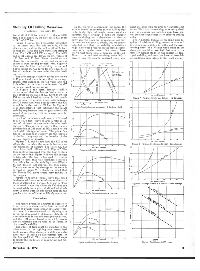
Figure 3 shows the hydrostatic properties of the intact hull. For this example, all the sides are vertical for the hull depth of 22 feet, so that the WPA and KP1 curves are straight lines. The DOB and LCF are equal. The MT1 and MH1 curves are drawn for KG values of 6.75 feet and 50 feet. Three conditions are shown for the stability curves, and on each is shown a wind heeling moment Mw. Figure 4 illustrates the intact hull stability curves, and a ratio under the GZ curve for KG equal to 50 feet of 1.4 times the area under the wind heel- ing curve.
The bow damage stability curves are shown in Figure 5 and it can be seen that the damage caused little change in the GZ value and had little effect on the area ratio 'between the GZ curve and wind heeling curve.
In Figure 6 the stern damage stability curves reveal that the damage had a catastro- phic effect on the ratio of GZ curve at 50-feet
KG to the wind heeling curve. In this condi- tion, in order to achieve a safe ratio between the GZ curve and wind heeling curve, the KG would be in the order of 25 feet. In Figure 6 it is demonstrated that satisfying the intact stability requirement does not guarantee a safe vessel. A satisfactory KG for damage must be calculated.
In all of the above conditions, a KG equal to KB (6.75 feet) curve showed a ratio in ex- cess of 1.4 times the area under the wind heel- ing curve. This, of course, proves that the ap- proximation of GM equal to BM should not be used with this type of vessel. The prime fac- tors in the change in stability are the location of the lost buoyancy and the location of the vertical center of gravity.
Figures 7, 8, and 9 show how the KG value affects the trim when the vessel is heeling dur- ing conditions of damage. The effect KG has on an intact hull is illustrated in Figure 7. The trim angle is measured from the bow to stern on the centerline. Figure 8 shows the change in trim when the bow is damaged. It is inter- esting to note that this damaged condition has little effect on the stability curve (Figure 5), but does in fact improve the trim angle.
The change caused by damage to the stern is covered in Figure 9. It should be noted that the 50-foot KG curve reacts very rapidly to heel angles.
Figure 10 shows a typical curve that could be developed from a series of curves similar to those illustrated in Figures 4, 5, and 6. This curve would show the allowable KG that can be used safely for a given draft and wind vel- ocity. A curve such as this would simplify the problems facing offshore mobile rig operators.
Conclusions
The results presented illustrate the necessity to accurately evaluate and include the vertical center of gravity when preparing stability cal- culations. It is recommended that righting arm curves 'be developed to determine stability of a vessel in both intact and damaged conditions, and that GM values based on intact hydrosta- tics calculations not be used as an indicator of a vessel's stability.
The effect of trim must be included in the calculations of the righting arm versus heel angle curves. Also, damaged stability calcula- tions must be based on hydrostatics data for the damaged hull. This requires several steps to satisfy the conditions of equilibrium and dis- placement.
In the course of researching this paper, the authors found the casualty rate on drilling rigs to be fairly high. Although, many casualties occurred while drilling, a sufficient number occurred during tow to give concern to the sta- bility analysis. Data on the causes of loss dur- ing tow are not easy to obtain, but we cannot help but feel that the stability calculations might have been prepared on the same assump- tions as a regular vessel. Our results have shown that these vessels, because of the ad- ditional trim and heel resulting when KG is greater than KB, must be analyzed using more
MTi" & MHi* [FT KIPS) 600 800 1000
Figure 3—Hydrostatic properties of the intact hull. t !
Mw X / \
HEEL ANGLE (DEGREES)
Figure 4—Stability curves—no damage.
JSfii«75_F r ) -L Jfe / \ 5 10 15 20 25 30 35 40
HEEL ANGLE (DEGREES)
Figure 5—Stability curves—bow damage.
KG - 6 75 f r —!dw__ >• k i -/-— \ \ \ exact methods than required for standard ship forms. This fact is becoming more recognized, and the classification societies now have spe- cial stability requirements for offshore drilling units.
The American Bureau of Shipping now re- quires all offshore drilling vessels to have suf- ficient reserve stability to withstand the over- turning effect of a 50-knot wind while in the damaged condition. We feel that now is the time for further study on the subject of dam- aged stability, and trust we have at least laid a foundation upon which to start such a study. / i / / 5 10 15 30 25 30 35
HEEL ANGLE(DEGREES)
Figure 7—Change in trim due to heel—no damage. / h. / ? gj / /
HEEL ANGLE (DEGREES)
Figure 8—Change in trim due to heel—bow damage.
HEEL ANGLE (DEGREES)
Figure 9—Change in trim due to heel—stern damage.
N&q, 5 10 15 20 25 30 35 40
HEEL ANGLE. (DEGREES)
Figure 6—Stability curves—stern damage.
DRAFT
Figure 10—Allowable KG curve.
November 15, 1973 15
