
Page 22: of Maritime Reporter Magazine (December 1977)
Read this page in Pdf, Flash or Html5 edition of December 1977 Maritime Reporter Magazine
 21
21
 23
23
General Dynamics Develops Manufacturing Concept For
Series Production Of Aluminum LNG Spheres
P. Takis Veliotis *
In the fall of 1972 General Dy- namics signed the first contracts in the United States for the con- struction of 125,000 cubic meter liquefied natural gas (LNG) car- riers. Subsequently, in 1973 and 1976, contracts for additional ves- sels were signed for a total of 12 ships.
This series of essentially du- plicate vessels would require 60 identical 120-foot-diameter alumi- num cargo containment spheres, five for each ship, to be manufac- tured at the rate of 20 spheres per year. In order to achieve this production and, at the same time, maximize the rate of ship deliver- ies, it was necessary to make the most efficient use of resources. A plan was therefore developed whereby the ships would be con- structed by experienced shipbuild- ers while the spheres would be built simultaneously, but offsite by an experienced sphere builder, then transported by barge to the shipyard and loaded into the com- pleted hull.
This concept required extensive modernization of the shipyard.
An automated standard parts fab- rication shop, two 875 by 150-foot building basins and a 1,200-ton
Goliath crane for loading of the spheres into the ships and han- dling ship modules were installed.
Concurrent with the moderni- zation of the shipyard facilities, a sphere subcontractor was se- lected and Charleston, S.C., was chosen as the manufacturing site.
The sphere subcontractor began facility work in 1973, with pro- duction scheduled to begin in 1974.
By September 1974 it became evi- dent that the subcontractor would be unable to meet contractural re- quirements. The shipyard there- fore freed itself of relationships with the subcontractor by assum- ing the responsibility for building the spheres.
During the last three months of 1974, the shipyard undertook an around-the-clock planning ef- fort which also drew upon re- sources from other divisions of the corporation. This effort had three phases: (1) the definition and evaluation of alternative methods to obtain LNG spheres; (2) selection and concurrent de- velopment of the manufacturing process and facility requirement for those alternative methods hav- ing the highest potential for suc- cess and cost effectiveness, and (3) final selection and implemen- tation of the optimum method to obtain LNG spheres.
Criteria for evaluation included: (1) capital investment required; (2) high confidence that the se- lected manufacturing plan would work; (3) flexibility in produc- tion process; (4) earliest and most rapid rate of sphere deliv- eries, and (5) acceptable risk.
Against these criteria, the fol- lowing possible alternatives were evaluated: (1) build spheres at the Charleston site; (2) build spheres at a new site; (3) build spheres at a new facility con- tiguous to the shipyard; (4) build spheres in the ship, and (5) se- lect another subcontractor to build spheres at the Charleston site or at a new facility.
This evaluation indicated that the shipyard could build spheres either at Charleston or at a new site at a rate equal to or faster than the original sphere subcon- tractor with a higher confidence in obtaining scheduled deliveries. / \ I \ ) \ y
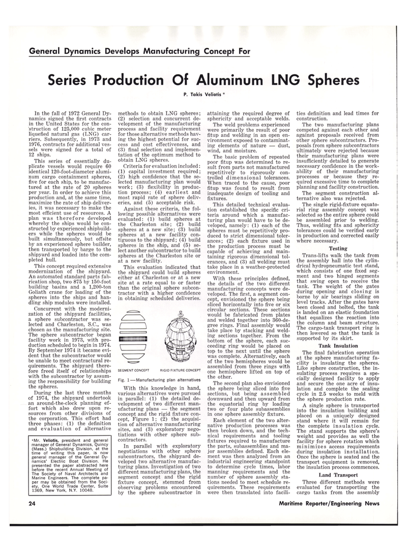
SEGMENT CONCEPT
Fig. 1 — Manufacturing plan alternatives
With this knowledge in hand, various alternatives were pursued in parallel: (1) the detailed de- velopment of two different man- ufacturing plans — the segment concept and the rigid fixture con- cept, Figure 1; (2) the acquisi- tion of alternative manufacturing sites, and (3) exploratory nego- tiations with other sphere sub- contractors.
In parallel with exploratory negotiations with other sphere subcontractors, the shipyard de- veloped two alternative manufac- turing plans. Investigation of two different manufacturing plans, the segment concept and the rigid fixture concept, stemmed from observing problems encountered by the sphere subcontractor in attaining the required degree of sphericity and acceptable welds.
The weld problems experienced were primarily the result of poor fitup and welding in an open en- vironment exposed to contaminat- ing elements of nature — dust, wind, and moisture.
The basic problem of repeated poor fitup was determined to re- sult from parts not manufactured repetitively to rigorously con- trolled dimensional tolerances.
When traced to the cause, poor fitup was found to result from inadequate design of tooling and fixtures.
This detailed technical evalua- tion established the specific cri- teria around which a manufac- turing plan would have to be de- veloped, namely: (1) each of the spheres must be repetitively pro- duced to strict dimensional toler- ances; (2) each fixture used in the production process must be capable of achieving and main- taining rigorous dimensional tol- erances, and (3) all welding must take place in a weather-protected environment.
With these principles defined, the details of the two different manufacturing concepts were de- veloped. The first, a segment con- cept, envisioned the sphere being sliced horizontally into five or six circular sections. These sections would be fabricated from plates and welded together into 360-de- gree rings. Final assembly would take place by stacking and weld- ing sections together. From the bottom of the sphere, each suc- ceeding ring would be placed on top to the next until the sphere was complete. Alternatively, each of the two hemispheres would be assembled from three rings with one hemisphere lifted on top of the other.
The second plan also envisioned the sphere being sliced into five sections, but being assembled downward and then upward from the equatorial ring by loading two or four plate subassemblies in one sphere assembly fixture.
Each element of the two alter- native production processes was then broken down, and the tech- nical requirements and tooling fixtures required to manufacture the parts, subassemblies and ma- jor assemblies defined. Each ele- ment was then analyzed from an industrial engineering standpoint to determine cycle times, labor manning requirements and the number of sphere assembly sta- tions needed to meet schedule re- quirements. These requirements were then translated into facili- ties definition and lead times for construction.
The two manufacturing plans competed against each other and against proposals received from other sphere subcontractors. Pro- posals from sphere subcontractors ultimately were rejected because their manufacturing plans were insufficiently detailed to generate necessary confidence in the work- ability of their manufacturing processes or because they re- quired excessive time to complete planning and facility construction.
The segment construction al- ternative also was rejected.
The single rigid-fixture equato- rial ring assembly concept was selected so the entire sphere could be assembled prior to welding.
Thus, welding fits and sphericity tolerances could be verified early in production and corrected easily where necessary.
Testing
Trans-lifts walk the tank from the assembly hall into the cylin- drical hydropneumatic test stand, which consists of one fixed seg- ment and two hinged segments that swing open to receive the tank. The weight of the gates during opening and closing is borne by air bearings sliding on level tracks. After the gates have been closed and bolted, the tank is landed on an elastic foundation that equalizes the reaction into the column and beam structure.
The cargo-tank transport ring is then lowered so that the tank is supported by its skirt.
Tank Insulation
The final fabrication operation at the sphere manufacturing fa- cility is insulating the spheres.
Like sphere construction, the in- sulating process requires a spe- cially designed facility to apply and secure the one acre of insu- lation and complete the sealing cycle in 2.5 weeks to meld with the sphere production rate.
A single sphere is transported into the insulation building and placed on a uniquely designed stand where it will remain for the complete insulation cycle.
The stand supports the sphere's weight and provides as well the facility for sphere rotation which minimizes access requirements during insulation installation.
Once the sphere is seated and the transport equipment is removed, the insulation process commences.
Land Transport
Three different methods were evaluated for transporting the cargo tanks from the assembly *Mr. Veliotis, president and general manager of Genera! Dynamics, Quincy (Mass.) Shipbuilding Division, at the time of writing this paper, is now general manager of the General Dy- namics' Electric Boat Division. He presented the paper abstracted here before the recent Annual Meeting of
The Society of Naval Architects and
Marine Engineers. The complete pa- per may be obtained from the Soci- ety, One World Trade Center, Suite 1369, New York, N.Y. 10048.
RIGID FIXTURE CONCEPT 24 Maritime Reporter/Engineering News
