Page 12: of Maritime Reporter Magazine (June 1980)
Read this page in Pdf, Flash or Html5 edition of June 1980 Maritime Reporter Magazine
 11
11
 13
13
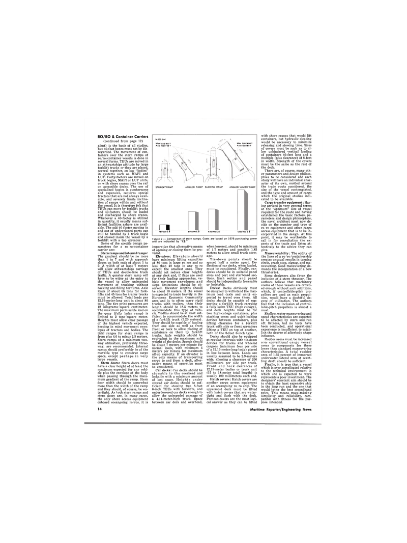
14 000 dwt
Max load 160 T
Axle load 65 T
Max load 400 T
Axle load 65 T
STRAIGHT RAMP n 160 000 E S
ANGLED RAMP SLEWING RAMP ANGLED "JUMBO'RAMP 550 000 E S 630 000 E S 1200 000 E $
Figure 2 — Comparison of stern ramps. Costs are based on 1978 purchasing power and are indicated by "E$."
RO/RO & Container Carriers (continued from page 12) alent) is the basis of all studies, but 40-foot boxes must not be dis- regarded. The movement of con- tainers over the stern ramps of ro/ro/container vessels is done in several forms. TEUs are moved in an athwartships attitude by large forklift trucks or they are placed, several together, on low "bodies" in systems such as MAFI and
LUF. Forty-footers are moved on truck bogies, MAFI or LUF units, or with shore cranes over the rail on accessible decks. The use of specialized bogies is cumbersome and expensive, requires special tractors that are not always avail- able, and severely limits inclina- tion of ramps within and without the vessel. It is therefore felt that
TEUs can move by forklift trucks and 40-footers should be loaded and discharged by shore cranes.
Whenever a 40-footer is utilized in quantity, it usually means suf- ficient facilities ashore are avail- able. The odd 40-footer moving in and out of undeveloped ports can still be handled by a truck bogie and stowed inside the vessel by a forklift with a top spreader.
Some of the specific design pa- rameters for a ro/ro/container carrier are:
Stern ramps and internal ramps:
The gradient should be no more than 1 to 7 and with approach slopes on both ends of about 1 to 9. A width of at least 7 meters will allow athwartships carriage of TEUs and double-lane truck traffic. A quarter stern ramp will have to be wider at the entry to the vessel to allow unimpeded movement of trucking without backing and filling for turns. Axle loads of about 65 tons for fork- lifts and 45 tons for trailer trucks must be allowed. Total loads per 12.19-meter-long unit is about 80 tons. The tire print pressures are 12 kilograms/square centimeter.
The maximum permissible load on the quay (fully laden ramp) is limited to 2 tons/square meter.
Heights must allow clear passage of the highest vehicle expected, keeping in mind movement enve- lopes of tractors and bodies. The tidal ranges for stern ramps is from plus 4.0 to minus 2.5 meters.
Stern ramps of a minimum two- way utilization, preferably three- way, are recommended. Internal ramps should preferably be of the movable type to conserve cargo space, except perhaps in very large vessels.
Stern doors: Stern doors must have a clear height of at least the maximum expected for any vehi- cle plus the envelope of the body when passing through the maxi- mum gradient of the ramp. Stern door width should be somewhat more than the width of the ramp and they should, of course, be wa- tertight. As both stern ramps and stern doors are, in many cases, the only shore access equipment onboard oceangoing ro/ros, it is imperative that alternative means of opening or closing them be pro- vided.
Elevators: Elevators should have minimum lifting capacities of 80 tons in large ro/ros and no less than 40 tons in any ro ro except the smallest ones. They should not reduce clear heights at any deck and, if flaps are used for their loading approaches, ve- hicle movement envelopes and slope limitations should be ob- served. Elevator lengths should be about 18 meters. If the vessel is expected to trade heavily in the
European Economic Community area and is to often carry rigid trucks with trailers, then their length should be 18.5 meters to accommodate this type of vehi- cle. Widths should be at least suf- ficient to accommodate the width of a forklift truck (3.20 meters).
They should be capable of loading from one side as well as from front or back to allow placing of containers on them by forklift trucks. Axle weights should be equivalent to the maximum axle weight of the decks. Speeds should be about 7 meters per minute for normal loads, with minimum 4 meters per minute for maximum all-up capacity. If an elevator is the only means of transporting cargo to and from a deck, alter- native means of operation must be considered.
Car decks: Car decks should be stowable to the overhead and lockable with a minimum amount of lost space. Heights under stowed car decks should be suf- ficient for stowing two 8-foot 6-inch TEUs with forklifts, and under lowered car decks enough to allow the unimpeded passage of a 4.11-meter-high truck. Space between car deck and overhead, when lowered, should be minimum of 1.7 meters and possible 1.85 meters to allow small truck stow- age.
Tie-down points should be spaced half a meter apart. De- flection of car decks, when loaded, must be considered. Finally, car- decks should be in suitable panel sizes and port and starboard sec- tions. Each section and panel should be independently lowerable or hoistable.
Decks: Decks obviously must be designed to withstand the max- imum load (axle and unit) ex- pected to travel over them. All decks should be capable of sup- porting a forklift truck carrying a fully laden TEU (high cubage), and deck heights must be for two high-cubage containers, plus stacking cones and quick-locking devices between containers, plus lifting clearance for a forklift truck with side or front spreaders lifting a TEU on top of another, both of the 8-foot 6-inch type.
Decks should also be equipped at regular intervals with tie-down devices for trucks and wheeled cargoes (minimum four per side of a 12.19-meter-long body) placed in line between lanes. Lanes are usually assumed to be 2.9-meters wide, allowing a clearance of 200 millimeters per side per truck.
Front and back clearances of 12.19-meter bodies or truck unit (15 to 18-meter total length) is usually 100 millimeters each end.
Hatch covers: Hatch covers are another cargo access equipment of an oceangoing ro, ro ship. The uppermost deck must be fitted with hatch covers that are water- tight and flush with the deck.
Pontoon covers are the most logi- cal answer as they can be lifted with shore cranes that would lift containers, but hydraulic cleating would be necessary to minimize releasing and stowing time. Sizes of covers must be such as to al- low unhindered vertical loading of containers 40-feet long and a multiple (plus clearance) of 8-feet in width. Strength of the covers must be the same as the rest of the deck.
There are, of course, many oth- er parameters and design philoso- phies to be considered and each study will have an individual char- acter of its own, molded around the trade route considered, the size of the vessel contemplated, and the type and amount of cargo which the original studies indi- cated to be available.
Cargo transfer equipment: Hav- ing arrived in very general terms at the "optimum" size of vessel required for the route and having established the basic factors, pa- rameters and design philosophies, the naval architect must now de- cide on the number and type of ro ro equipment and other cargo access equipment that is to be in- corporated in the design. At this point, it may be worthwhile to call in for consultation the ex- perts of the trade and listen at- tentively to the advice they can give.
Maneuverability: The oddity of the lines of a ro/ro/containership creates unusual results in turning circle, crash stop, zigzag, and ma- neuvering. Good maneuvering de- mands the incorporation of a bow thruster(s).
Some designers also favor the inclusion of a stern thruster. The authors believe that machinery rooms of these vessels are crowd- ed enough without such additions, which, if controllable-pitch pro- pellers are used as main propul- sion, would have a doubtful de- gree of utilization. The authors feel that the inclusion of control- lable-pitch propellers is almost a must.
Shallow-water maneuvering and speed characteristics are expected to be affected by stern and run aft flatness, but no tests have been conducted, and operational experience is insufficient to estab- lish the degree of afterbody shape influence.
Rudder areas must be increased over conventional cargo vessel areas to compensate for these lower than standard maneuvering characteristics. A total rudder area of 1.65 percent of immersed underwater lateral area at scant- ling draft should be sufficient.
Finally, it is true that a vessel which is over-complicated relative to the technical environment in which she is expected to work represents a poor investment. The designers' constant aim should be to obtain the least expensive ship in the long run and the one that would bring the best secondhand price. This means maximizing simplicity and reliability, com- patible with fitness for the pur- pose intended. 14 Maritime Reporter/Engineering News
