Page 13: of Maritime Reporter Magazine (September 15, 1980)
Read this page in Pdf, Flash or Html5 edition of September 15, 1980 Maritime Reporter Magazine
 12
12
 14
14
sophisticated designs in special- ized trades.
The five scheduled phases of this design project are: Phase 1 — Development of mobilization ship capabilities ; Phase 2 — Pre- liminary design of mobilization ship; Phase 3 — Contract design of mobilization ship; Phase 4 —
Construction of prototype, and
Phase 5—Operation of prototype.
The first phase has been com- pleted and has resulted in the development of working papers reviewing: Needed shipping capa- bilities ; shipyard production prob- lems, engineering system alterna- tives ; possible ship concepts, and design constraints.
The second phase has also been completed. It began with the de- velopment of three conceptual de- signs—the PD-204 versatile gen- eral cargo mobilization designs.
These cargo ships were planned as candidates for the basic build- ing blocks of the mobilization fleet. These designs were devel- oped through the concept stages to assure feasibility. The three designs offered a variety of ship sizes and cargo-handling arrange- ments. Features of the three de- signs developed were compared with each other for their partic- ular advantages and disadvan- tages.
The small PD-204 design, "500
General," featured a 489-foot LBP and 73.5-foot beam vessel with five general cargo holds.
The large PD-204 design, "670
RO/RO," had a 655-foot LBP and 105-foot beam and was designed primarily for roll-on / roll-off cargo.
The middle sized "550 Combi- nation," on the other hand, was 539-feet in LBP and 97-feet in beam and had a multipurpose cargo-handling approach. Eight holds with 'tween decks were serviced by cranes (or kingposts and booms) with hatch covers forming a container-guide struc- ture, which when in a vertical po- sition, allows easy loading of con- tainers. A stern ramp was also provided for roll-on/roll-off cargo access to the second deck.
Efforts between August 1977 and November 1978 refined the 550 Combination design into the
Multi-Purpose Mobilization Ship preliminary design, PD-214.
In September 1979 a contract was awarded to M. Rosenblatt &
Son, Inc. to prepare the contract design of the base ship and a number of alternative versions utilizing various optional types of propulsion machinery and cargo gear. This work is scheduled to be completed some time after the presentation of this paper.
The preliminary design was the starting point for developing the contract design. The object of the contract design phase is to com- plete the preparation of plans and specifications to a level of detail adequate for a shipyard to pro- duce a bid quotation to construct the ship.
As a result of the Government/
Industry Mobilization Ship Con- ference in November 1978, nu- merous comments were received which indicated that the prelim- inary design was too small for both commercial and military op- erations. Comparison with the re- sults of MarAd R&D study on the design of the next generation cargo liner also indicated that a larger vessel would be more ap- propriate for commercial use. This
R&D study is particularly valid since it was done in cooperation with seven ship operators.
It was concluded that the new contract design base ship length should be the same as the pre- liminary design jumbo. In addi- tion, the beam was increased to 105 feet 6 inches. It became ap- parent that, for more efficient container stowage, the hull depth should be increased to 70 feet, and it was decided to use flush, mechanically operated hatch cov- ers on the weather deck and to include a ramp to allow vehicle access to the weather deck. Fi- nally, the hull material was changed from mild steel to high- strength steel when it was found to be readily available in mobili- zation situations. The design is shown in Figure 1.
General Arrangement
The preliminary design of the
Multi-Purpose Mobilization Ship is a single-screw ship capable of (continued on page 16)
U.S. Coast Guard Approved
Oil/Water /j Separators *
Recovered Oil pay-back.
The value of the recovered oil, either returned directly to the ship's fuel tank or stored for reprocessing ashore, should not be overlooked.
The pay-back period for
SFC-BW Separators is continually being reduced as the price of oil rises.
Get all the Facts.
SFC BW Oil/Water
Separators are available with capacities from Vi to 60 cubic meters per hour. Write or call for full details ... and for a copy of "From A to X about
Oil/Water Separators". This six-page report has facts on
MARPOL, IMCO, and U.S. regulations for shipboard oil/water separators.
Butterworth
Systems
Butterworth Systems Inc. 224 Park Ave., RO. Box 352
Florham Park, N.J. 07932 USA
Phone: (201)765-1546
Cable: BUTTWORTH
NEW YORK TLX 136434
Butterworth Systems (UK) Ltd. 445 Brighton Road,
South Croydon, Surrey,
CR2 6EU. ENGLAND
Phone: 01-668-6211
Cable: MAROPEDOK
CROYDON TLX 946524
Societe d'Etudes et de Realisations d'Equipements Petroliers 11, rue du Pont V 76600 LeHavre, France
Phone: (35)25.81.15
Telex: Sotran 190571 F
Less Than 2 ppm of Oil. unattended are also available.
Every SFC BW unit is equipped with a dedicated feed pump to allow SFC BW
Separators to be sized to meet a vessel's exact needs.
They do not have to rely on the vessel's bilge pump.
BUTTERWORTH
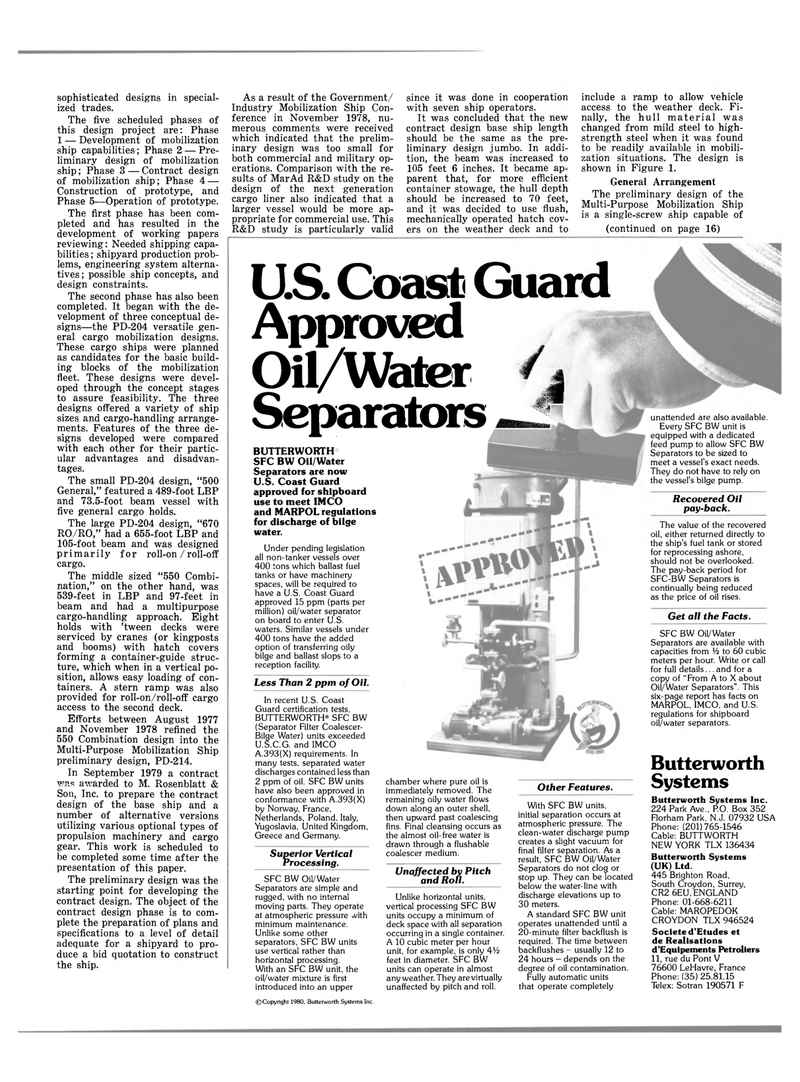
SFC BW Oil/Water
Separators are now
U.S. Coast Guard approved for shipboard use to meet IMCO and MARPOL regulations for discharge of bilge water.
Under pending legislation all non-tanker vessels over 400 tons which ballast fuel tanks or have machinery spaces, will be required to have a U.S. Coast Guard approved 15 ppm (parts per million) oil/water separator on board to enter U.S. waters. Similar vessels under 400 tons have the added option of transferring oily bilge and ballast slops to a reception facility.
In recent U.S. Coast
Guard certification tests,
BUTTERWORTH19 SFC BW (Separator Filter Coalescer-
Bilge Water) units exceeded
U.S.C.G. and IMCO
A.393(X) requirements. In many tests, separated water discharges contained less than 2 ppm of oil. SFC BW units have also been approved in conformance with A.393(X) by Norway, France,
Netherlands, Poland. Italy,
Yugoslavia, United Kingdom,
Greece and Germany.
Superior Vertical
Processing.
SFC BW Oil/Water
Separators are simple and rugged, with no internal moving parts. They operate at atmospheric pressure *vith minimum maintenance.
Unlike some other separators, SFC BW units use vertical rather than horizontal processing.
With an SFC BW unit, the oil/water mixture is first introduced into an upper chamber where pure oil is immediately removed. The remaining oily water flows down along an outer shell, then upward past coalescing fins. Final cleansing occurs as the almost oil-free water is drawn through a flushable coalescer medium.
Unaffected by Pitch and Roll.
Unlike horizontal units, vertical processing SFC BW units occupy a minimum of deck space with all separation occurring in a single container.
A 10 cubic meter per hour unit, for example, is only 4Vi feet in diameter. SFC BW units can operate in almost any weather. They are virtually unaffected by pitch and roll.
Other Features.
With SFC BW units, initial separation occurs at atmospheric pressure. The clean-water discharge pump creates a slight vacuum for final filter separation. As a result, SFC BW Oil/Water
Separators do not clog or stop up. They can be located below the water-line with discharge elevations up to 30 meters.
A standard SFC BW unit operates unattended until a 20-minute filter backflush is required. The time between backflushes - usually 12 to 24 hours - depends on the degree of oil contamination.
Fully automatic units that operate completely ©Copyright 1980, Butterworth Systems Inc.
