
Page 8: of Maritime Reporter Magazine (October 1980)
Read this page in Pdf, Flash or Html5 edition of October 1980 Maritime Reporter Magazine
 7
7
 9
9
St. Louis Ship Delivers
The 'John M. Donnelly7 To
Ingram Barge Company
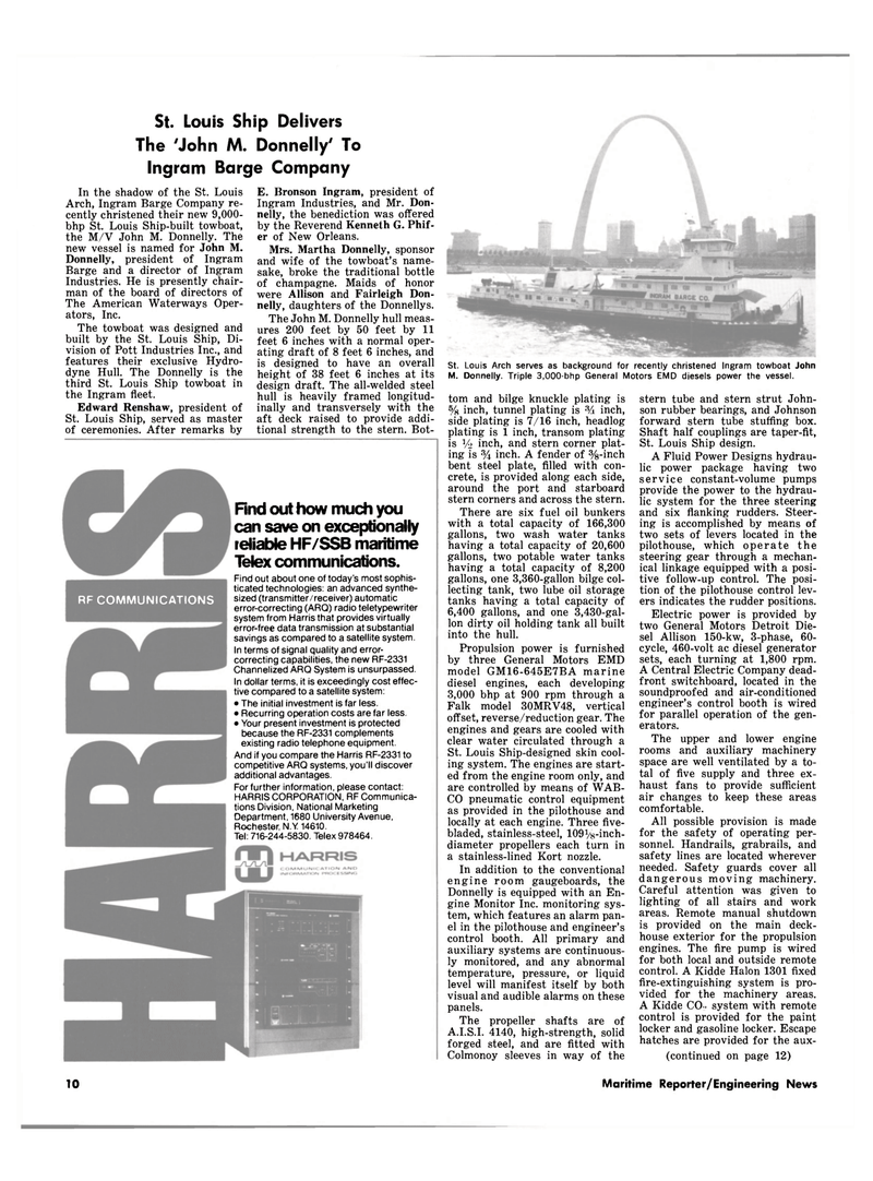
St. Louis Arch serves as background for recently christened Ingram towboat John
M. Donnelly. Triple 3,000-bhp General Motors EMD diesels power the vessel.
In the shadow of the St. Louis
Arch, Ingram Barge Company re- cently christened their new 9,000- bhp St. Louis Ship-built towboat, the M/V John M. Donnelly. The new vessel is named for John M.
Donnelly, president of Ingram
Barge and a director of Ingram
Industries. He is presently chair- man of the board of directors of
The American Waterways Oper- ators, Inc.
The towboat was designed and built by the St. Louis Ship, Di- vision of Pott Industries Inc., and features their exclusive Hydro- dyne Hull. The Donnelly is the third St. Louis Ship towboat in the Ingram fleet.
Edward Renshaw, president of
St. Louis Ship, served as master of ceremonies. After remarks by
E. Bronson Ingram, president of
Ingram Industries, and Mr. Don- nelly, the benediction was offered by the Reverend Kenneth G. Phif- er of New Orleans.
Mrs. Martha Donnelly, sponsor and wife of the towboat's name- sake, broke the traditional bottle of champagne. Maids of honor were Allison and Fairleigh Don- nelly, daughters of the Donnellys.
The John M. Donnelly hull meas- ures 200 feet by 50 feet by 11 feet 6 inches with a normal oper- ating draft of 8 feet 6 inches, and is designed to have an overall height of 38 feet 6 inches at its design draft. The all-welded steel hull is heavily framed longitud- inally and transversely with the aft deck raised to provide addi- tional strength to the stern. Bot- tom and bilge knuckle plating is % inch, tunnel plating is inch, side plating is 7/16 inch, headlog plating is 1 inch, transom plating is V-2 inch, and stern corner plat- ing is % inch. A fender of %-inch bent steel plate, filled with con- crete, is provided along each side, around the port and starboard stern corners and across the stern.
There are six fuel oil bunkers with a total capacity of 166,300 gallons, two wash water tanks having a total capacity of 20,600 gallons, two potable water tanks having a total capacity of 8,200 gallons, one 3,360-gallon bilge col- lecting tank, two lube oil storage tanks having a total capacity of 6,400 gallons, and one 3,430-gal- lon dirty oil holding tank all built into the hull.
Propulsion power is furnished by three General Motors EMD model GM16-645E7BA marine diesel engines, each developing 3,000 bhp at 900 rpm through a
Falk model 30MRV48, vertical offset, reverse/reduction gear. The engines and gears are cooled with clear water circulated through a
St. Louis Ship-designed skin cool- ing system. The engines are start- ed from the engine room only, and are controlled by means of WAB-
CO pneumatic control equipment as provided in the pilothouse and locally at each engine. Three five- bladed, stainless-steel, 109Vs-inch- diameter propellers each turn in a stainless-lined Kort nozzle.
In addition to the conventional engine room gaugeboards, the
Donnelly is equipped with an En- gine Monitor Inc. monitoring sys- tem, which features an alarm pan- el in the pilothouse and engineer's control booth. All primary and auxiliary systems are continuous- ly monitored, and any abnormal temperature, pressure, or liquid level will manifest itself by both visual and audible alarms on these panels.
The propeller shafts are of
A.I.S.I. 4140, high-strength, solid forged steel, and are fitted with
Colmonoy sleeves in way of the stern tube and stern strut John- son rubber bearings, and Johnson forward stern tube stuffing box.
Shaft half couplings are taper-fit,
St. Louis Ship design.
A Fluid Power Designs hydrau- lic power package having two service constant-volume pumps provide the power to the hydrau- lic system for the three steering and six flanking rudders. Steer- ing is accomplished by means of two sets of levers located in the pilothouse, which operate the steering gear through a mechan- ical linkage equipped with a posi- tive follow-up control. The posi- tion of the pilothouse control lev- ers indicates the rudder positions.
Electric power is provided by two General Motors Detroit Die- sel Allison 150-kw, 3-phase, 60- cycle, 460-volt ac diesel generator sets, each turning at 1,800 rpm.
A Central Electric Company dead- front switchboard, located in the soundproofed and air-conditioned engineer's control booth is wired for parallel operation of the gen- erators.
The upper and lower engine rooms and auxiliary machinery space are well ventilated by a to- tal of five supply and three ex- haust fans to provide sufficient air changes to keep these areas comfortable.
All possible provision is made for the safety of operating per- sonnel. Handrails, grabrails, and safety lines are located wherever needed. Safety guards cover all dangerous moving machinery.
Careful attention was given to lighting of all stairs and work areas. Remote manual shutdown is provided on the main deck- house exterior for the propulsion engines. The fire pump is wired for both local and outside remote control. A Kidde Halon 1301 fixed fire-extinguishing system is pro- vided for the machinery areas.
A Kidde CO- system with remote control is provided for the paint locker and gasoline locker. Escape hatches are provided for the aux- (continued on page 12)
RF COMMUNICATIONS
Find out how much you can save on exceptionally reliable HF/SSB maritime
Telex communications.
Find out about one of today's most sophis- ticated technologies: an advanced synthe- sized (transmitter/receiver) automatic error-correcting (ARQ) radio teletypewriter system from Harris that provides virtually error-free data transmission at substantial savings as compared to a satellite system.
In terms of signal quality and error- correcting capabilities, the new RF-2331
Channelized ARQ System is unsurpassed.
In dollar terms, it is exceedingly cost effec- tive compared to a satellite system: • The initial investment is far less. • Recurring operation costs are far less. • Your present investment is protected because the RF-2331 complements existing radio telephone equipment.
And if you compare the Harris RF-2331 to competitive ARQ systems, you'll discover additional advantages.
For further information, please contact:
HARRIS CORPORATION, RF Communica- tions Division, National Marketing
Department, 1680 University Avenue,
Rochester, N.Y 14610.
Tel: 716-244-5830. Telex 978464.
TO Maritime Reporter/Engineering News
