
Page 98: of Maritime Reporter Magazine (November 1985)
Read this page in Pdf, Flash or Html5 edition of November 1985 Maritime Reporter Magazine
 97
97
 99
99
The Most Rugged and Accurate
Monitor of Oil-In-Water in the Industry
Applications include monitoring of:
Bilge water discharge, boiler feed water, condensale returns, cooling systems for high-speed diesel engines and on-shore run-off water.
PROPULSION UPDATE
Renk Gear System Provides
Constant-Frequency Power
Generation From Main Engine 10 HC
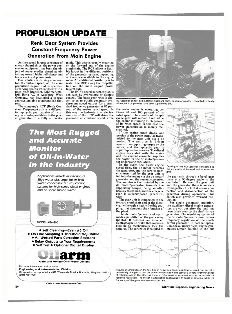
Results of simulation on the test bed of heavy sea conditions. Engine speed (top curve) is periodically changed so that the dc motor operates in one case as a generator (minus sense of rotation) and in the other as a motor (plus sense of rotation) in order to provide the required regulation. The motor is alternating continuously itc sense of rotation, while the frequency of the generator remains constant.
Maritime Reporter/Engineering News
As the second largest consumer of energy aboard ships, the power gen- eration equipment has been the ob- ject of many studies aimed at ob- taining overall higher efficiency and lower electrical power costs.
One solution is driving a genera- tor, at constant speed, off the main propulsion engine that is operated at varying speeds when fitted with a fixed-pitch propeller. Zahnraederfa- brik Renk AG of Augsburg, West
Germany, has developed a special gear system able to accomplish that result.
The company's RCF (Renk Con- stant Frequency) unit is a differen- tial epicyclic gear capable of insur- ing constant-speed drive to the pow- er generator in a fully automatic mode. This gear is usually mounted on the forward end of the engine crankshaft. The RCF allows a flexi- ble layout in five different positions of the generator system, depending on the space available in the engine room. An additional possibility is to install the RCF along the propeller line on the main engine power takeoff side.
The RCF's speed superposition is achieved by hydrostatic or electric control. The basic gear ratio is cho- _ sen so as to obtain generator syn- RCF gearbox on test bed in Renk's Augsburg plant. Generator/motor is mounted vertically, chronous speed output for a stan- All electric components have been supplied by BBC. dard frequency generator at 85 per- cent of the engine rated speed. In this way the hydrostatic or electric controls of the RCF will drive the generator at constant speed while
MODEL #BA-200 • Self Cleaning—Even #6 Oil • On Line Sampling • Threshold Adjustable • All Wetted Parts Corrosion Resistant • Relay Outputs to Your Requirements • Self Test • Optional Digital Display arm
Alarm and Monitor Oil-ln-Water Content
For more information call or write:
Engineering and Instrumentation Division
Biospherics Incorporated • 4928 Wyaconda Road • Rockville, Maryland 20852 (301)770-7700
Circle 113 on Reader Service Card 104
Drawing of the RCF gearbox connected to the generator at forward end of main en- gine. the gear unit through a bevel gear train at a 90-degree angle to the crankshaft. Between the gear unit and the generator there is an elec- tromagnetic clutch that allows con- nection and disconnection of the generator during operation. This clutch also provides overload pro- tection.
For single generator operation, the auxiliary diesel engine genera- tors are cut out after the load has been taken over by the shaft-driven generator. The regulating system of the dc motor/generator now insures frequency regulation of the shaft- driven generator. In parallel opera- tion, the auxiliary diesel engine gen- erators remain coupled to the bus the main engine is operating be- tween 70 and 100 percent of its rated speed. The annulus of the epi- cyclic gear will remain fixed while the engine is running at 85 percent of its rated speed; in this case the power transmission is merely me- chanical.
If the engine speed drops, one portion of the power output is trans- mitted to the gear unit via a dc motor. The annulus is driven against the supporting torque by the motor, and the epicyclic gear is superimposed motorwise. The diesel engine associated with the mains and the current converter supplies the power for the dc motor/genera- tor undergoing regulation.
In the event the diesel engine speed rises, the dc motor becomes the generator, and the surplus pow- er transmitted by the gear unit is fed into the mains via the dc motor/ generator and the current converter.
The annulus is then rotated by the dc motor/generator towards the supporting torque, being simulta- neously restrained, and the epicyclic gear is superimposed generator- wise.
The gear unit is connected to the forward crankshaft end of the diesel engine through a highly flexible cou- pling that dampens the vibration of the plant.
The dc motor/generator of verti- cal design is fitted on the gear casing (photo). It features an attached electromagnetic brake that makes it possible to mechanically lock the annulus. The generator is coupled to
