Page 52: of Maritime Reporter Magazine (July 15, 1986)
Read this page in Pdf, Flash or Html5 edition of July 15, 1986 Maritime Reporter Magazine
 51
51
 53
53
ELECTRONICS
UPDATE
Integrated Ship Electronic Systems —Literature Available—
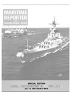
The bridge of most ships contains a varied assortment of individual instruments for navigation, moni- toring and ship control which have been added, one or two at a time, over the years to meet carriage re- quirements and perceived needs.
This multiplicity of equipment, with different layouts and proce- dures from ship to ship, can lead to confusion and occasional errors, as bridge watchstanders must rush back and forth from one station to another.
It has long been recognized that a movement toward standardization and integration would be desirable for bridge electronics. Integrated bridge systems, which bring to- gether in one place the coordinated information and data from various sources, would greatly enhance the safe and efficient operation of the vessel, while reducing workloads and minimizing human error.
A leader in this area has been the
Racal Marine Group, which has been developing and manufacturing commercial marine navigation and radar equipment since the mid- 19408 and has been working on inte- gration in these devices for many years. In 1971, Racal started a de- velopment program on an inte- grated bridge system, called MA-
NAV, which received support from the U.K. government and culmi- nated in sea trials on the ship Esso
Mersey. These were in general suc- cessful, the system receiving the ap- proval of ship's staff, who especially appreciated the ready interaction between an automatic chart table and the radar display. But the con- cept was judged to be ahead of its time, and production was not un- dertaken although a military ver- sion was developed for the British and other navies.
A decade later, Racal decided that the time was ripe for another look at the integrated bridge. A short feasi- bility study confirmed this and rec- ommended that the project should be extended to cover three other principal operational areas of a ship.
Accordingly, in 1982, an R&D effort was set in motion, looking into the use of electronics in the four ship operating areas—bridge, machinery spaces, cargo and administration.
This resulted in three-month sea trials aboard the ship British Trent.
Concentrating on the two main areas of bridge and machinery, the trials aimed to foresee the principals and requirements of the 1990s.
The integrated bridge electronics developed out of this program in- cluded a workstation comprising a high-definition color graphic VDU acting as a command display and showing the master or watch officer a composite picture of the immedi- ate information he needs: course, under-keel clearance, distance/ course to next waypoint, speed, en- gine RPMs, etc. This involved two computers and associated VDU and keyboards, with inputs from a Ra- cal-Decca ARPA, compass, log, Dec- ca Navigator, satnav and engine room sensors, with outputs to the
ARPA, autopilot and satellite com- munications terminal. Ship's posi- tion was displayed both in latitude/ longitude and pictorially on the electronic chart, and the auto-route keeping was included, with altera- tions being made automatically be- tween waypoints. An economics page could be called up on the com- puter, giving an assessment of per- formance and economics via bar graphs comparing the actual per- formance with results of the ship's original sea trials in terms of fuel consumption, propulsive power at a particular speed and fuel consump- tion vs. distance through the water.
In turn, this information was con- verted into economic terms based on fuel costs. From this, it was pos- sible to see such things as the degree of performance degradation due to hull fouling and the effect of speed and trim alterations. This was con- sidered a useful tool for a master in costing the results of operational decisions. Data could be trans- mitted automatically at high speed to the company's head office via sat- ellite.
On the British Trent, the ship's staff found the command display to be very useful and were of the opin- ion that the presentation generally gave all required information to the watch officer. Within certain limita- tions, the electronic chart worked well, and many of its facilities were also appreciated. There was general agreement, however, that this pre- sentation could not currently super- sede the standard paper chart. The presentation of passage economics aroused most interest, giving ship's staff an increased awareness of the importance of cost as a function of speed. This would help them make more economic speed decisions.
The valuable experience gained on these sea trials was embodied in the specification which laid the foundations of the full development of Racal's new integrated ship elec- tronic system (ISES). This is a "family" of systems covering the bridge, engine room, cargo and ship administration, through stand- alone systems or as an intercon- nected network. An essential ele- ment in this family is the integrated bridge electronic system (IBES).
The IBES includes a navigational positioning system, an ARPA radar, an autopilot and an optional auto- matic chart table. It is available in two versions—the basic IBES 100 and the more extensive IBES 1000.
IBES 100 is centered on the Ra- cal-Decca MNS 2000 marine navi- gation receiver, which integrates
Decca, Loran-C, Transit, Omega and dead reckoning, depending on available input data and position on the earth's surface. This processor is connected to the ARPA, on which the operator can view, on demand, a video presentation of a cross-track error and intended track. It can also be connected to a Racal-Decca ref- erenced adaptive autopilot to pro- vide automatic track keeping. The automatic chart table, when fitted, shows the ship's position contin- uously as a spot of light projected below onto a standard hydrographic chart. Up to 100 waypoints can be stored, and the ship can steer auto- matically along prescribed routes.
In addition, own-ship's position,
GMT, course, speed and the next five waypoints are all continually available in digital form for use by other devices, such as an EPIRB and administrative area systems, if fitted.
The IBES 1000 is centered on one or more workstations, each includ- ing a color graphic display and pow- erful data processing capabilities.
These communicate with an ARPA, autopilot, automatic chart table and other navigational sensors. The small but powerful processor unit that drives the system is able to operate up to five workstations.
Each workstation consists of a color monitor with an extremely flexible page accessing system, a specialized keyboard and cursor control device.
They can be free-standing, table- top or console mounted, with the processor fitted internally or as a separate unit.
Other hardware included in a typ- ical IBES 1000 consists of two inter- switched radars, one of which is nor- mally an ARPA, one MNS 2000 navigation receiver, one automatic chart table, one adaptive autopilot and associated steering system, and two gyrocompasses. Optional equip- ment includes a printer for data log- ging and additional radar displays.
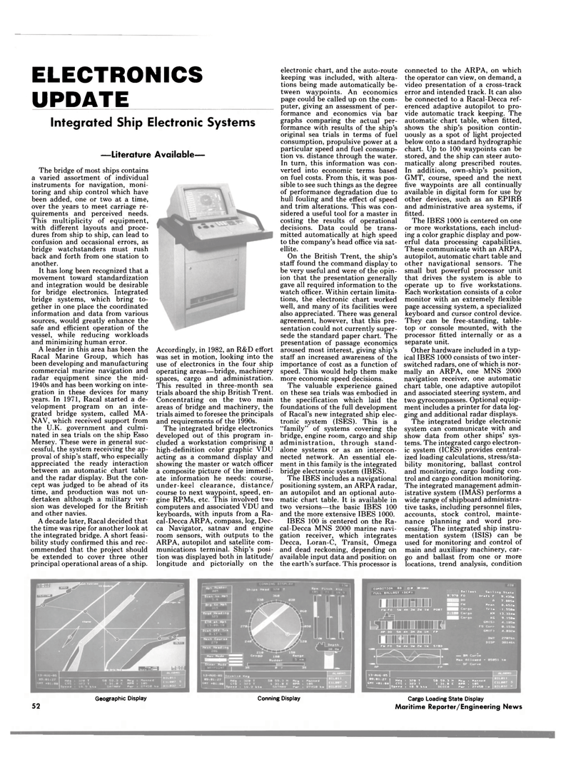
The integrated bridge electronic system can communicate with and show data from other ships' sys- tems. The integrated cargo electron- ic system (ICES) provides central- ized loading calculations, stress/sta- bility monitoring, ballast control and monitoring, cargo loading con- trol and cargo condition monitoring.
The integrated management admin- istrative system (IMAS) performs a wide range of shipboard administra- tive tasks, including personnel files, accounts, stock control, mainte- nance planning and word pro- cessing. The integrated ship instru- mentation system (ISIS) can be used for monitoring and control of main and auxiliary machinery, car- go and ballast from one or more locations, trend analysis, condition
CONDITION 8D D «F i rULL BALLAST (DEP) Bo I last 0.970 FO
FM FO 5M 4H 3W 2W 1W PORT
Sai1ln9 Slate Draft F 9.435.
A 7.885m Mean 8.652a
Trim -1.550. KM 13.334.
KG 9.150.
AP DO 5H 4H 3H 2H 1H FP
FU FO 5H 4U 3M 2M 114 STBD 13-fiUC-85 09:01:27 | Hdg . 320 T GMT +01:08 CTS : 323 T [Speed! 18.9 kti 50 59.3 N 1 31.0 E
DECCA
Mcy Manned RPM : 105
Pmr : 27450 I
Geographic Display Conning Display 52
Cargo Loading State Display
Maritime Reporter/Engineering News
