
Page 44: of Maritime Reporter Magazine (February 1994)
Read this page in Pdf, Flash or Html5 edition of February 1994 Maritime Reporter Magazine
 43
43
 45
45
PROPULSION UPDATE
Propeller Selection For
Diesel Electric Machinery
Diesel electric machinery has become more common in newbuilding projects in the last few years. The vessels are normally cruisers or ferries that have a high auxiliary electric power consumption. Also, vessels with high power demand for cargo han- dling, such as tankers, may be suit- able for electric drive.
This article will highlight some of the most important aspects con- cerning fixed pitch (fp) propellers and controllable pitch (cp) propel- lers for diesel electric machinery, not only from a hydrodynamic point of view but also mechanical, such as propeller shaft arrangement and vibrations.
Propeller Layout
From the propeller viewpoint the diesel electric machinery has the advantage of continuous variable speed over the whole range from 0 to + or -100 percent rpm. Another advantage is that 100 percent torque can often be utilized within the whole operating range. One disad- vantage is that it is not possible to utilize over-speed, due to electrical limitations.
For the above reason the fp pro- peller must be designed to reach the MCR point at trial condition, i.e. full load, clean hull and calm weather.
In order to operate at full power in various sea margin conditions, the propulsion system is normally calculated for 10 to 20 percent over- torque.
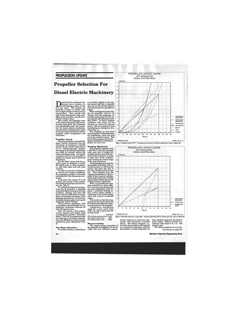
In practice this means 10 to 20 percent over-sizing of the propel- ler/shaftline/gear/motors/convert- ers, etc. (Fig. 1).
For a diesel mechanical arrange- ment the fp propeller is designed somewhat light-running at the trial condition, making sure that full power can be reached also in condi- tions of increased resistance (hull fouling/wind and sea). In trial con- dition the diesel engine's over-speed capability will be utilized.
Diesel electric machinery with cp propellers should ideally have a pitch/rpm combinator between 65 and 100 percent rpm.
This will secure a fast maneu- vering response and simple shaft arrangement (further described below). The CPP arrangement does not need any over-torque capacity, since the MCR point always can be reached by pitch adjustment (Fig. 2).
One Motor Operation
For safety reasons, a redundancy 110 is normally applied to the elec- tric motors and this is typically done by two 50 percent motors, mounted in line or in parallel via a gear.
When running one motor only, the fp propeller will be too "heavy" and the maximum al- lowable torque limit for the mo- tor and gear will reduce the avail- able power. In heavy weather condition this limit will be reached at about 30 percent power. This is a rather low level considering an emergency situ- ation (Fig. 1).
This tendency is even more pronounced for a diesel mechani- cal installation, since the load curve for a diesel is lower. This is one of the reasons why multi- diesel installations with fp pro- pellers are very rare.
Stopping Maneuvers
A fp propeller together with a DE drive must be equipped with some sort of torque ab- sorption system, normally elec- trical brake resistors, in order to take care of the "turbine" power during the initial stage of the stop maneuver.
As the stopping proceeds, the fp propeller will work with re- versed rotation at 100 percent torque, but since the rpm is low, the utilized power is also low. This explains why the stopping properties of a fp pro- peller is poor and not substan- tially improved by the variable speed control, which comes with a diesel electric machinery.
With a cp propeller the stop- ping maneuver is more effec- tive. As soon as the ahead pitch has been reduced by a few de- grees, a powerful braking ac- tion occurs which reaches a maximum at low pitch setting, with full power available astern.
The result is that the stop- ping time and head reach can be reduced considerably with a cp compared to a fp propeller.
Comparative calculations made for a twin screw ferry with Loa=180 m gives the fol- lowing result:
Head reach
FPP w/ diesel mechanical drive . 612m
FPP w/diesel electric drive 492m
CPP w/diesel electric drive 384m
PROPELLER LAYOUT CURVE
FPP INSTALLATION
DIESEL ELECTRIC DRIVE
POWER (%) 110 / k /! t f. i : ; :
I : ' t : ' : :
J : • t : i • i t : ' ! ' ;
J ! i t ' 1 / /
A L* S ' / \y / ;> / / / + : JT j Si. / / ' i A/i / / \ / A i / jZ / / .jf : : : » / •»: > Zk/
Ay 1 1 : 1 1 1 : 1 1 1 : 1 1 1 1 1 1 1 1 1 : 1 1 1 1 II : 1 1 1 1 1 1 120%TORQUE
ONE MOTOR 100% TORQUE
ONE MOTOR 120%TORQUE — 100%TORQUE 30% SM
TRIAL ..... TOWING 10 20 30 40 50 60 70 80 90 100 110 120 130
RPM (%)
KAMEWA AB/HMP FPPDE1 93-10-11
Fig. 1: Propeller layout for FPP. The towing curve will vary for different applications. (Source: KaMeWa AB)
PROPELLER LAYOUT CURVE
CPP INSTALLATION
DIESEL ELECTRIC DRIVE 130 120 110 90
POWER (%) ! /i ; / i / ; / / ; /:
L" 1 / ^ ^^ / i / f I ! i
J/1 i iii 1 i
M 1 : 1 1 1 i 1 1 1 i 1 1 1 i 1=1 1 i 1 1 1 i 1 1 1 i 1 1 1 1 1 I : 1 1 1 1 1 100% TORQUE
ONE MOTOR 100%TORQUE
COMBINATOR
CURVE 0 10 20 30 40 50 60 70 80 90 100 110 120 130
RPM (%)
KAMEWA AB / HMP CPPDE 93-10-18
Fig. 2: Combinator layout for a cp propeller. Variable speed interval 65 to 100 percent rpm. (Source: KaMeWa AB)
Maneuverability
The maneuvering properties of the propeller installation can be di- vided into two different aspects: thrust response or maneuver com- mand; and maximum available thrust. The thrust response, i.e., how fast the propellers will respond on a maneuver command, with the fp propeller is solely dependent on time needed to increase the electric motor speed. Fifteen seconds is a common value from 0 to + or - 100 percent rpm.
The thrust response of a cp pro- (Continued on page 56)
Maritime Reporter/Engineering News
