Page 42: of Maritime Reporter Magazine (May 1997)
Read this page in Pdf, Flash or Html5 edition of May 1997 Maritime Reporter Magazine
PROPULSION GUIDE
Siemens Podded Electric
Drive Provides Operational
Advantages
Siemens AB Marine Engineering has developed a new propulsion system with- in the power range of 5 to 30 MW per unit, which it claims is proven to offer a better efficiency level than conventional propellers, in addition to improved maneuver- ability, increased safety and improved handling.
The Siemens Schottel Propulsor (SSP) is especially suited to cruise vessels, large ferries and passen- ger vessels, and cargo vessels including chemical tankers, icego- ing vessels, large offshore struc- tures and navy vessels.
Siemens reports that with this system, energy savings of more than 10 percent are possible due to the efficiency improvements of the combination of Schottel Twin pro- pellers and the newly developed
Siemens permanent excited syn- chronous motor, allowing maxi- mum efficiency in transmission of electrical energy at minimum installation space. This statistic is based on tank tests and model sim- ulations for a 70,000-gt cruise liner.
SSP Machinery
The 14-MW Siemens Schottel
Propulsor consists of a streamlined lower housing made from ship- building steel and cast steel. Two fins are welded to the lower hous- ing to gain rotational energy from the forward propeller.
The lower housing of the unit is designed in such a way that it allows a safe underwater mounting of the lower housing so that no dry- docking is necessary for disman- tling of the lower unit.
The upper part consists of a cone type support structure flanged to the ship's structure and made from shipbuilding steel.
Control cubicle
Azimuth control /Slip ring unit
Auxiliaries
Rear propeller
Support to ship's structure
Power supply
Longitudinal flow motor
LFM motor
Front propeller
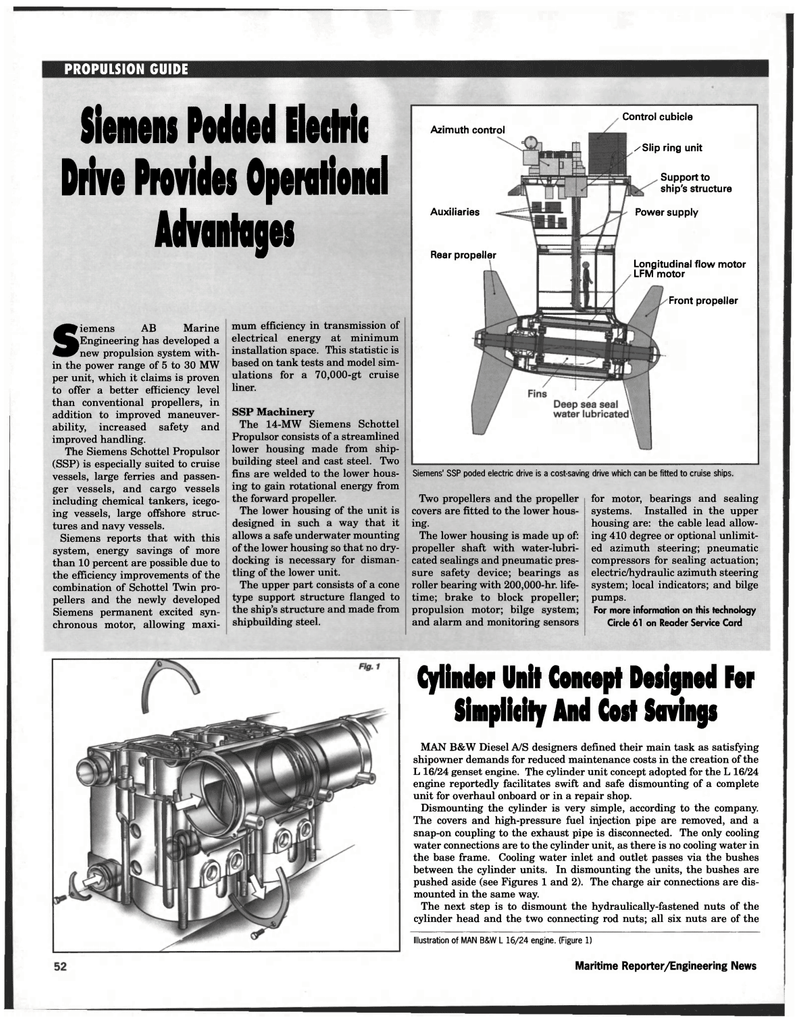
Siemens' SSP poded electric drive is a cost-saving drive which can be fitted to cruise ships.
Two propellers and the propeller covers are fitted to the lower hous- ing.
The lower housing is made up of: propeller shaft with water-lubri- cated sealings and pneumatic pres- sure safety device; bearings as roller bearing with 200,000-hr. life- time; brake to block propeller; propulsion motor; bilge system; and alarm and monitoring sensors for motor, bearings and sealing systems. Installed in the upper housing are: the cable lead allow- ing 410 degree or optional unlimit- ed azimuth steering; pneumatic compressors for sealing actuation; electric/hydraulic azimuth steering system; local indicators; and bilge pumps.
For more information on this technology
Circle 61 on Reader Service Card
Illustration of MAN B&W L 16/24 engine. (Figure 1)
Maritime Reporter/Engineering News
Cylinder Unit Concept Designed Fer
Simplicity And Cost Savings
MAN B&W Diesel A/S designers defined their main task as satisfying shipowner demands for reduced maintenance costs in the creation of the
L 16/24 genset engine. The cylinder unit concept adopted for the L 16/24 engine reportedly facilitates swift and safe dismounting of a complete unit for overhaul onboard or in a repair shop.
Dismounting the cylinder is very simple, according to the company.
The covers and high-pressure fuel injection pipe are removed, and a snap-on coupling to the exhaust pipe is disconnected. The only cooling water connections are to the cylinder unit, as there is no cooling water in the base frame. Cooling water inlet and outlet passes via the bushes between the cylinder units. In dismounting the units, the bushes are pushed aside (see Figures 1 and 2). The charge air connections are dis- mounted in the same way.
The next step is to dismount the hydraulically-fastened nuts of the cylinder head and the two connecting rod nuts; all six nuts are of the

 41
41

 43
43
