
Page 77: of Maritime Reporter Magazine (January 1998)
Read this page in Pdf, Flash or Html5 edition of January 1998 Maritime Reporter Magazine
 76
76
 78
78
SHIP & BOATBUILDING TECHNOLOGY
Approach To Engine Room Dosign
This is the second article in a four-part series describing a pro- ject executed by the U.S. Navy in partnership with domestic and international shipyards, shipown- er/operators and marine equip- ment vendors. As mentioned in the first article, the project involved an
Engine Room Arrangement Model (ERAM) study, sponsored by the
Mid-Term Strategic Sealift
Technology Development Program (MTSSTDP) and orchestrated by the Shipbuilding Technology
Department of the David Taylor
Model Basin (DTMB).
The vision of the project was to initiate a customer-focused process that would enable the U.S. ship- building industry to design and build engine rooms which would promote internationally competi- tive commercial ships.
The objectives were: • To provide a forum for U.S. shipbuilders to present views and needs for product and process design; • To develop, within 12 months, a process using Integrated Process and Product Development (IPPD) for industry use; • To design engine room arrangements that provide the basis for the design of internation- ally competitive commercial ships; • To demonstrate, within 24 months, the process by designing three (later increased to four) world-class engine room arrange- ments; • To achieve customer-focus and buy-in of product design;
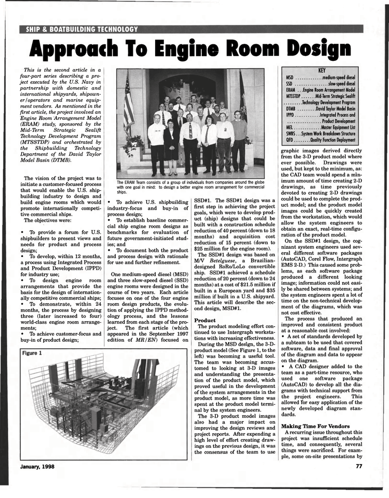
The ERAM Team consists of a group of individuals from companies around the globe with one goal in mind: to design a better engine room arrangement for commercial ships. • To achieve U.S. shipbuilding industry-focus and buy-in of process design; • To establish baseline commer- cial ship engine room designs as benchmarks for evaluation of future government-initiated stud- ies; and • To document both the product and process design with rationale for use and further refinement.
One medium-speed diesel (MSD) and three slow-speed diesel (SSD) engine rooms were designed in the course of two years. Each article focuses on one of the four engine room design products, the evolu- tion of applying the IPPD method- ology process, and the lessons learned from each stage of the pro- ject. The first article (which appeared in the September 1997 edition of MR/EN) focused on
SSD#1. The SSD#1 design was a first step in achieving the project goals, which were to develop prod- uct (ship) designs that could be built with a construction schedule reduction of 40 percent (down to 18 months) and acquisition cost reduction of 15 percent (down to $25 million for the engine room).
The SSD#1 design was based on
M/V Betelguese, a Brazilian- designed RoRo/LoLo convertible ship. SSD#1 achieved a schedule reduction of 20 percent (down to 24 months) at a cost of $21.5 million if built in a European yard and $35 million if built in a U.S. shipyard.
This article will describe the sec- ond design, MSD#1.
Product
The product modeling effort con- tinued to use Intergraph worksta- tions with increasing effectiveness.
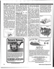
During the MSD design, the 3-D- product model (See Figure 1, to the left) was becoming a useful tool.
The team was becoming accus- tomed to looking at 3-D images and understanding the presenta- tion of the product model, which proved useful in the development of the system arrangements in the product model, as more time was spent at the product model termi- nal by the system engineers.
The 3-D product model images also had a major impact on improving the design reviews and project reports. After expending a high level of effort creating draw- ings on the previous design, it was the consensus of the team to use
KEY
MSD .. medium-speed diesel
SSD .. slow-speed diesel
ERAM . .Engine Room Arrangement Model
MTSSTDP Mid-Term Strategic Sealift .Technology Development Program
DTMB . David Taylor Model Basin
IPPD.. Integrated Process and
Product Development
MEL... Master Equipment List
SWBS.. .System Work Breakdown Structure
QFD Quality Function Deployment
January, 1998 graphic images derived directly from the 3-D product model where ever possible. Drawings were used, but kept to the minimum, as: the CAD team would spend a min- imum amount of time creating 2-D drawings, as time previously devoted to creating 2-D drawings could be used to complete the prod- uct model; and the product model images could be quickly created from the workstation, which would allow the system engineers to obtain an exact, real-time configu- ration of the product model.
On the SSD#1 design, the cog- nizant system engineers used sev- eral different software packages (AutoCAD, Corel Flow, Intergraph
EMS 2-D.) This caused some prob- lems, as each software package produced a different looking image; information could not easi- ly be shared between systems; and the system engineers spent a lot of time on the non-technical develop- ment of the diagrams, which was not cost effective.
The process that produced an improved and consistent product at a reasonable cost involved: • A set of standards developed by a subteam to be used that covered software, data and final approval of the diagram and data to appear on the diagram. • A CAD designer added to the team as a part-time resource, who used one software package (AutoCAD) to develop all the dia- grams with technical support from the project engineers. This allowed for easy application of the newly developed diagram stan- dards.
Making Time For Vendors
A recurring issue throughout this project was insufficient schedule time, and consequently, several things were sacrificed. For exam- ple, some on-site presentations by 77
