Page 42: of Maritime Reporter Magazine (March 1998)
Read this page in Pdf, Flash or Html5 edition of March 1998 Maritime Reporter Magazine
(buise Lihe strategy. To start, the company held a design competition which tasked three renowned ship designers with providing a concept of the new ship, a concept to be presented to company CEO
Michael Eisner. Following the selection of the "best relevant direction" for the design to proceed, the same three designers went back to work, from which the first tangible example of the Disney fleet emerged, (time frame: seven months, April to October 1994).
Simultaneously, a series of other critical interior and exterior design decisions were being made. Design resources from inside and outside
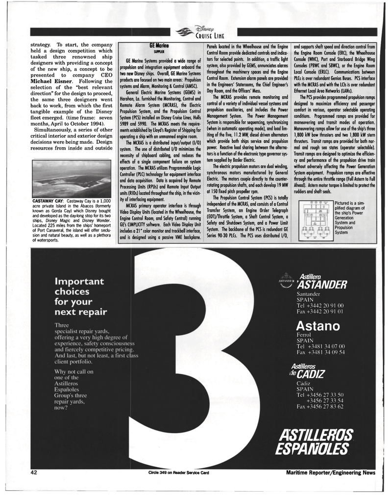
CASTAWAY CAY: Castaway Cay is a 1,000 acre private Island in the Abacos (formerly known as Gorda Cay) which Disney bought and developed as the day-long stop for its two ships, Disney Magic and D/sney Wonder.
Located 225 miles from the ships' homeport of Port Canaveral, the island will offer seclu- sion and natural beauty, as well as a plethora of watersports.
GE Marine
SUPPUER
GE Marine Systems provided a wide range of propulsion and integration equipment onboard the two new Disney ships. Overall, GE Marine Systems products are focused on two main areas: Propulsion systems and Alarm, Monitoring & Control (AMSC).
General Electric Marine Systems (GEMS) in
Harahan, La. furnished the Monitoring, Control and
Remote Alarm System (MCRAS), the Electric
Propulsion System, and the Propulsion Control
System (PCS) installed on Disney Cruise Lines, Hulls 5989 cind 5990. The MCRAS meets the require- ments established by Lloyd's Register of Shipping for operating a ship with an unmanned engine room.
The MCRAS is a distributed input/output (I/O) system. The use of distributed I/O minimizes the necessity of shipboard cabling, and reduces the effects of a single component failure on system operation. The MCRAS utilizes Programmable Logic
Controller (PLC) technology for equipment interface and data acquisition. Data is acquired by Remote
Processing Units (RPUs) and Remote Input Output units (RIOs) located throughout the ship, in the vicin- ity of interfacing equipment.
MCRAS primary operator interface is through
Video Display Units (located in the Wheelhouse, the
Engine Control Room, and Safety Central) running
GE's CIMPLICITY software. Each Video Display Unit includes a 21" color monitor and trackball interface, and is designed using a passive VME backplane.
Panels located in the Wheelhouse and the Engine
Control Room provide dedicated controls and indica- tors for selected points. In addition, a traffic light system, also provided by GEMS, annunciates alarms throughout the machinery spaces and the Engine
Control Room. Extension alarm panels are provided in the Engineers' Staterooms, the Chief Engineer's
Day Room, and the Officers' Mess.
The MCRAS provides remote monitoring and control of o variety of individual vessel systems and propulsion auxiliaries, and includes the Power
Management System. The Power Management
System is responsible for sequencing, synchronizing (when in automatic operating mode), and load lim- iting of the five, 11.2 MW, diesel driven alternators which provide both ships service and propulsion power. Reactive load sharing between the alterna- tors is a function of the electronic type governor sys- tem supplied by Basler Electric.
The electric propulsion motors are dual winding, synchronous motors manufactured by General
Electric. The motors couple directly to the counter- rotating propulsion shafts, and each develop 19 MW at 150 fixed pitch propeller rpm.
The Propulsion Control System (PCS) is totally independent of the MCRAS, and consists of a Control
Transfer System, an Engine Order Telegraph (EOT)Ahrottle System, a Shaft Control System, a
Safety and Shutdown System, and a Power Limit
System. The backbone of the PCS is redundant GE
Series 90-30 PLCs. The PCS uses distributed 1/0, and supports shaft speed and direction control from the Engine Room Console (ERC), the Wheelhouse
Console (WHC), Port and Starboard Bridge Wing
Consoles (PBWC and SBWC), or the Engine Room
Local Console (ERLC). Communications between
PLCs is over redundant Genius Buses. PCS interface with the MCRAS and with the LCIs is over redundant
Ethernet Local Area Networks (LANs).
The PCS provides programmed propulsion ramps designed to maximize efficiency and passenger comfort in various, operator selectable operating conditions. Programmed ramps are provided for maneuvering and transit modes of operation.
Maneuvering ramps allow for use of the ship's three 1,800 kW bow thrusters and two 1,800 kW stern thrusters. Transit ramps are provided for both nor- mal and rough sea states (operator selectable).
Transit ramps are designed to optimize the efficien- cy and performance of the propulsion drive train without adversely affecting the Power Generation
System equipment. Propulsion ramps are effective through the entire throttle range (Full Astern to Full
Ahead). Astern motor torque is limited to protect the rudders and shaft seals.
Pictured is a sim- plified diagram of the ship's Power
Generation
System and
Propulsion
System
Circle 349 on Reader Service Card
Astillero w" ASTANDER
Santander
SPAIN
Tel +3442 20 91 OO
Fax+3442 20 91 01
Astano
Ferrol
SPAIN
Tel +348134 07 00
Fax +3481 34 09 54
Astilleros '"CADIZ
Cadiz
SPAIN
Tel +3456 27 33 50 +3456 27 33 54
Fax +3456 27 83 62
ASTILLEROS ESPANOLES
Maritime Reporter/Engineering News

 41
41

 43
43
