
Page 62: of Maritime Reporter Magazine (July 1998)
Read this page in Pdf, Flash or Html5 edition of July 1998 Maritime Reporter Magazine
 61
61
 63
63
CAD/CAM ERAM
This is the third article in a four-part series describing a project executed by the U.S. Navy in partnership with domestic and international shipyards, shipowner I operators and marine equipment vendors (the first two articles appeared in the September 1997 and January 1998 issues of MR/EN, respectively). The pro- ject involved an Engine Room Arrangement
Model (ERAM) study, sponsored by the Mid-
Term Strategic Sealift Technology Development
Program (MTSSTDP) and orchestrated by the
Shipbuilding Technology Department of the
David Taylor Model Basin (DTMB).
The vision of the project was to initiate a cus- tomer-focused process that would enable the
U.S. shipbuilding industry to design and build engine rooms that would promote international- ly competitive commercial ships.
One medium-speed diesel (MSD) and three slow-speed diesel (SSD) engine rooms were designed in the course of two years. Each arti- cle focuses on one of the four engine room design products, the evolution of applying the IPPD methodology process, and the lessons learned from each stage of the project.
The first article focused on SSD#1. The
SSD#1 design was a first step in achieving the project goals, which were to develop product (ship) designs that could be built with a con- struction schedule reduction of 40 percent (down to 18 months) and acquisition cost reduc- tion of 15 percent (down to $25 million for the engine room). The SSD#1 design was based on the M/V Betelgeuse; a Brazilian designed
RoRo/LoLo convertible ship. SSD#1 achieved a schedule reduction of 20 percent (down to 24 months) at a cost of $21.5 million if built in a
European yard and $35 million if built in an
U.S. shipyard. The second article focused on
MSD#1 which verified the repeatability of the design process. The MSD design utilized the
SSD#1 design as the baseline.
Although no further improvement in the con- struction schedule was reported, the use of a large level 3 unit (Level 3 units are defined as an assembly of equipment, valves, piping and electrical mounted on a secondary foundation with all local wiring installed, all of which are designed to be constructed in a shop) enhanced the probability of a further reduction in sched- ule and cost as is being realized on the Sealift
New Construction Program.
This article will describe the third design,
SSD#2.
Product
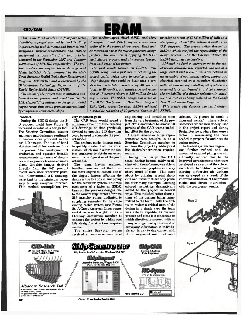
During the SDD#2 design the 3-
D product model (see Figure 1) increased in value as a design tool.
The Steering Committee, system engineers and designers continued to become more proficient in the use 3-D images. The use of hand sketches had all but vanished from the process. The development of production and operator friendly arrangements by teams of design- ers and engineers became common place. Graphic images derived directly from the 3-D product model were used wherever possi- ble. Conventional 2-D drawings were kept to the minimum neces- sary to keep everyone informed.
This method accomplished two very important goals.
The CAD team would spend a minimum amount of time creating 2-D drawings, as time previously devoted to creating 2-D drawings could be used to complete the prod- uct model.
The product model images could be quickly created from the work- station, which would allow the sys- tem engineers to obtain an exact, real-time configuration of the prod- uct model.
The team, having matured together, now realized that after the main engine is located; one of the biggest factors affecting the design is the location of and piping for the seawater system. This was even more of a factor on SSD#2 than on the previous designs due to the owners requirement for nine 215 cu.m./hr. pumps dedicated to supplying seawater to the cargo cooling reefer system (see Figure 2). A Great American Lines repre- sentative was brought in as a
Steering Committee member to enhance the project by adding real life design/construction require- ments.
The entire Seawater system received an extensive amount of engineering and modeling time from the very beginning of the pro- ject. This amounted to almost 20 percent of the CAD teams model- ing effort for the project.
A Great American Lines repre- sentative was brought in as a
Steering Committee member to enhance the project by adding real life design/construction require- ments.
During this design the CAD team, having become fairly profi- cient with the software, was able to create superior graphics in a very short period of time. This came about by utilizing several short- cuts and tricks that are only possi- ble after many attempts. Creating colored isometrics dramatically added to the project in several ways. This included better descrip- tions of the designs being trans- mitted to the team. With the abil- ity to review a critical area of the design in a single view the team was able to expedite its decision process and come to a consensus on which direction to proceed with on many arrangement questions. Also conveying information to individu- als not in day to day contact with the arrangement was much more ^htfr&J iM If VilOf Product Model & Nesting . ..... 3D Produc g inside AutoCAD R14 Ship Production Software for Windows 95 & NT
Assembly Structure, Weight & CG
BOM, Production Reports •A
O.
Albacore Research Ltd. \ 4196 Kashtan Place, Victoria, B.C., Canada, V8X 4L7
Toll Free: 1-888-210-7420
Tel: (250) 479-3638 Fax: (250) 479-0868
E-mail: [email protected] _5_J
Fairing & Lofting
Plate Expansion
NC Code Generation
Free Demo CD OAutodesk. 62 Circle 201 on Reader Service Card 62
Figure 3.
Figure 2. efficient, "A picture is worth a thousand words." These colored isometrics where now widely used in the project report and during
Design Reviews, where they were a factor in minimizing the time needed to prepare for and host the design review.
The fuel oil system (see Figure 3) was further refined and the amount of required piping was sig- nificantly reduced due to the improved arrangements that were developed as a result of the colored isometrics. In addition, a compact starting air/service air package was developed as a result of the improved utilization of the product model and direct interaction with the compressor vendor.
