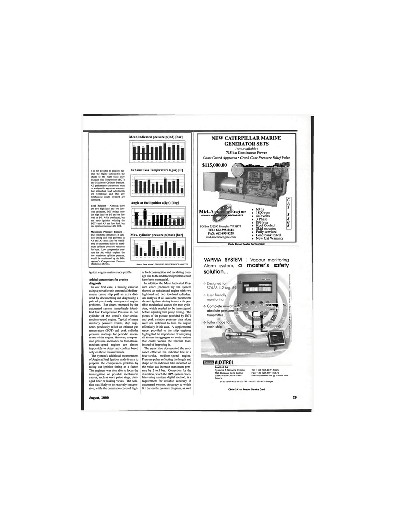
Page 29: of Maritime Reporter Magazine (August 1999)
Read this page in Pdf, Flash or Html5 edition of August 1999 Maritime Reporter Magazine
Mean indicated pressure p(ind) [bar] mi
It is not possible to properly bal- ance the engine indicated in the charts to the right using only
Exhaust Gas Temperature (EGT) and Maximum Cylinder Pressure.
All performance parameters must be analyzed in aggregate to ensure that individual load adjustments are beneficial—and that any mechanical issues involved are corrected.
Load Balance - Although there are two high-load and two low- load cylinders, EGT reflects only the high load on B2 and the low load on B6. A4 is overloaded, but has early ignition reducing the
EGT—and A3 has low load, but late ignition increases the EGT.
Maximum Pressure Balance -
The combined influences of igni- tion timing and load problems in
A4 and A3 must also be consid- ered to understand fully the maxi- mum cylinder pressure variances for both. Low compression pres- sure for A6, which explains the low maximum cylinder pressure, would be confirmed by the DPA system's Compression Pressure charts (not shown).
Exhaust Gas Temperature t(gas) [C]
Angle at fuel ignition a(ign) [deg] 35 3 • 25 • 15 • 3 2 1 i 2 .6 1 f 2.6 1 2.6 1 _ • - III 1.6 llll 1 li 1 1 1 • 1
A1 A2 A3 A4 A5 A6 B1 B2 B3 B4 B5 B6 |
Max. cylinder pressure p(max) [bar]
Source: Drew Marine's DPA DIESEL PERFORMANCE ANALYZE typical engine maintenance profile.
Added parameters for precise diagnosis
In our first case, a training exercise using a portable unit onboard a Mediter- ranean cruise ship paid an extra divi- dend by documenting and diagnosing a pair of previously unsuspected engine problems. Bar charts generated by the automated system immediately identi- fied low Compression Pressure in one cylinder of the vessel's four-stroke, medium-speed engine. Typical of many similarly powered vessels, ship engi- neers previously relied on exhaust gas temperature (EGT) and peak cylinder pressure readings for periodic assess- ments of the engine. However, compres- sion pressure anomalies on four-stroke, medium-speed engines are almost impossible to detect and confirm based only on those measurements.
The system's additional measurement of Angle at Fuel Ignition made it easy to pinpoint the compression problem by ruling out ignition timing as a factor.
The engineer was then able to focus the investigation on possible mechanical causes, such as worn piston rings, dam- aged liner or leaking valves. The solu- tion was likely to be relatively inexpen- sive, while the cumulative costs of high- er fuel consumption and escalating dam- age due to the undetected problem could have been substantial.
In addition, the Mean Indicated Pres- sure chart generated by the system showed an unbalanced engine with two high-load and two low-load cylinders.
An analysis of all available parameters showed ignition timing issues with pos- sible mechanical causes for two cylin- ders, which needed to be investigated before adjusting fuel pump timing. The pieces of the picture provided by EGT and peak cylinder pressure data alone were not sufficient to tune the engine effectively in this case. A supplemental report provided to the ship engineer highlighted the importance of analyzing all factors in aggregate to avoid actions that could worsen the thermal load, instead of improving it.
The report also documented the reso- nance effect on the indicator line of a four-stroke, medium-speed engine.
Pressure pulses reflecting the length and shape of the indicator tube mounted on the valve can increase maximum pres- sure by 2 to 5 bar. Correction for the distortion, which the DPA system calcu- lates using a unique digital method, is a requirement for reliable accuracy in automated systems. Accuracy to within 0.1 bar on the pressure diagram, as well
NEW CATERPILLAR MARINE
GENERATOR SETS (two available) 715 kw Continuous Power
Coast Guard Approved • Crank Case Pressure Relief Valve $115,000.00 x n i BlrffH
Mid-A ngme epccuu jers
PO Box 752590 Memphis TN 38175
TEL: 662-895-8444
FAX: 662-895-8228 mid-americaengine.com 60 hz 1800 rpm 440 volts 3 Phase 893 kva
Keel Cooled
Skid mounted
Fully serviced
Load bank tested
New Cat Warranty 3 5 0 8
Circle 264 on Reader Service Card
Auxitrol SA
Systems & Sensors Division 168, Bureaux de la Colline 92213 Saint-Cloud cedex
France
SA au capital de 25 000 000 FRF -
Tel + 33(0)1.49.11.65.75
Fax+ 33 (0)1.49.11.65.76
Email systemes.dir @ auxitrol.com 602 023 251 R.C.S Bourges
Circle 277 on Reader Service Card
Esterhne
VAPMA SYSTEM : Vapour monitoring
Alarm system, a master's safety solution... /-"» I . . MM NWli uni riUM 'IM«Ti- "o <3> Complete inovative • I absolute pressure 1 _ — . * transmitter • 'jlv.I Jmw fc
Al ll s <$> Tailor made for each ship I I P .. §
AUXITROL
August, 1999 29

 28
28

 30
30
