Page 67: of Maritime Reporter Magazine (September 1999)
Read this page in Pdf, Flash or Html5 edition of September 1999 Maritime Reporter Magazine
 66
66
 68
68
Naval Architecture & Marine Engineering
Ballast Water Exchange: Is There A Better Way?
The system consists of: 1] To provide a water inlet at Ship's Bow
End, introduce and lead clean water in water ballast tank through existing
Water Ballast Tank Main Line. 2] The water flowing in the tank with a certain positive pressure push away the biologically dirty water through the opening (Sea Chest), which is provided at forward bottom end of the tank.
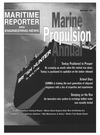
However, each of the ships has its own bottom structure formed by girders and floors. Model Tank tests were conduct- ed to confirm the influence of bottom structure in relation to the location of water inlet points in the tank (bell mouth). Tests conducted confirmed the speed at which the Ballast Water is exchanged through the use of red-col- ored water in the model Aframax ballast tank, which was constructed using trans- parent plastic (see photos).
Preliminary testing showed that approximately seven hours was suffi- cient to exchange 90 percent of the vol- ume of the water in a 3,500 cu. m. tank, with a 400 mm diameter Ballast Water
Main Line with the ship traveling 15 knots.
The model test was conducted for both single and double hulled Aframax tanker types, and it was confirmed that the most suitable location of the
Water Outlet is at the forward end of the tank to have the longest water path to achieve the water exchange most effectively.
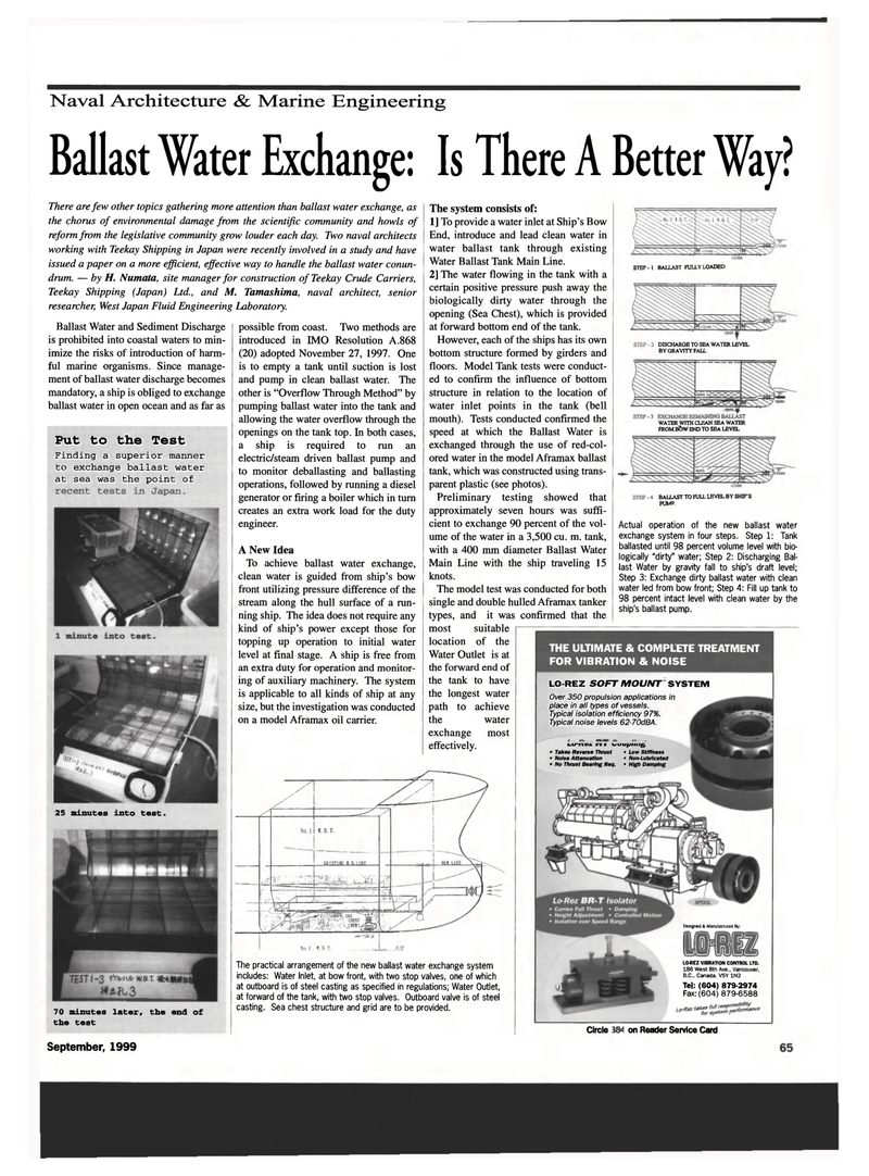
STEP - 1 BALLAST FULLY LOADED
DISCHARGE TO SEA WATER LEVEL
BY GRAVITY FALL
WATER WITH CLEAN SEA WATER
FROM B?>W END TO SEA LEVEL
BALLAST TO FULL LEVEL BY SHIP'S
PUMP.
Actual operation of the new ballast water exchange system in four steps. Step 1: Tank ballasted until 98 percent volume level with bio- logically "dirty" water; Step 2: Discharging Bal- last Water by gravity fall to ship's draft level;
Step 3: Exchange dirty ballast water with clean water led from bow front; Step 4: Fill up tank to 98 percent intact level with clean water by the ship's ballast pump.
THE ULTIMATE & COMPLETE TREATMENT
FOR VIBRATION & NOISE
LO-REZ SOFT MOUNT SYSTEM
Over 350 propulsion applications in place in all types of vessels.
Typical isolation efficiency 97%.
Typical noise levels 62-70dBA. w-nn n • i/iyuprnig • Takes Reverse Thrust • Low Stiffness • Noise Attenuation • Non-Lubricated • No Thrust Bearing Req. • High Damping
There are few other topics gathering more attention than ballast water exchange, as the chorus of environmental damage from the scientific community and howls of reform from the legislative community grow louder each day. Two naval architects working with Teekay Shipping in Japan were recently involved in a study and have issued a paper on a more efficient, effective way to handle the ballast water conun- drum. — by H. Numata, site manager for construction of Teekay Crude Carriers,
Teekay Shipping (Japan) Ltd., and M. Tamashima, naval architect, senior researcher, West Japan Fluid Engineering Laboratory.
Ballast Water and Sediment Discharge is prohibited into coastal waters to min- imize the risks of introduction of harm- ful marine organisms. Since manage- ment of ballast water discharge becomes mandatory, a ship is obliged to exchange ballast water in open ocean and as far as
Put to the Test
Finding a superior manner to exchange ballast water at sea was the point of possible from coast. Two methods are introduced in IMO Resolution A. 868 (20) adopted November 27, 1997. One is to empty a tank until suction is lost and pump in clean ballast water. The other is "Overflow Through Method" by pumping ballast water into the tank and allowing the water overflow through the openings on the tank top. In both cases, a ship is required to run an electric/steam driven ballast pump and to monitor deballasting and ballasting operations, followed by running a diesel generator or firing a boiler which in turn creates an extra work load for the duty engineer.
A New Idea
To achieve ballast water exchange, clean water is guided from ship's bow front utilizing pressure difference of the stream along the hull surface of a run- ning ship. The idea does not require any kind of ship's power except those for topping up operation to initial water level at final stage. A ship is free from an extra duty for operation and monitor- ing of auxiliary machinery. The system is applicable to all kinds of ship at any size, but the investigation was conducted on a model Aframax oil carrier. 25 minutes into test.
Circle 261 on Reader Service Card
September, 1999 69
L&REZ VIBRATION CONTROL LTD. 186 West 8th Ave., Vancouver,
B.C., Canada. V5Y 1N2
Tel: (604) 879-2974
Fax: (604) 879-6588 70 minutes later, the end of the test
The practical arrangement of the new ballast water exchange system includes: Water Inlet, at bow front, with two stop valves, one of which at outboard is of steel casting as specified in regulations; Water Outlet, at forward of the tank, with two stop valves. Outboard valve is of steel casting. Sea chest structure and grid are to be provided.
Designed & Manufactured By:
