
Page 34: of Maritime Reporter Magazine (January 2002)
Read this page in Pdf, Flash or Html5 edition of January 2002 Maritime Reporter Magazine
 33
33
 35
35
Surface Combatants Benefit from
Northrop Grumman Research
Northrop Grumman Corporation's Ship Systems sector reports that it has successfully tested the
Low Observable Multifunction Stack (LMS) designed to demonstrate two different advanced exhaust suppresser systems for surface combat- ants. The exhaust systems, enclosed in a low sig- nature composite structure, also integrate embed- ded multifunction communication arrays. "This integrated approach will help provide increased connectivity necessary for modern war- fare while avoiding the mass of communications antennas that typically cover the topside of sur- face combatants," said Richard Schenk, president of Ship Systems' Full Service Center.
Construction of the LMS was completed at the
Northrop Grumman Ship Systems Avondale
Operations composite facility in Gulfport, Miss., in July 2001. After completing construction, the
LMS structure was barged to Ship Systems'
Ingalls Operations' East Bank facility in
Pascagoula, Miss., for final fit-out, and land-based testing of its Radar Cross Section (RCS). The
RCS testing was performed at the Ship Systems
Near Field Radar Reflectivity Range (NFR3) facility. "The NFR3 facility was instrumental in demonstrating the performance of the LMS and greatly reduced the potential cost of testing at other East or West Coast facilities," said Ross
Buck, engineering project manager and Ship Sys- tems Radar Range Test director.
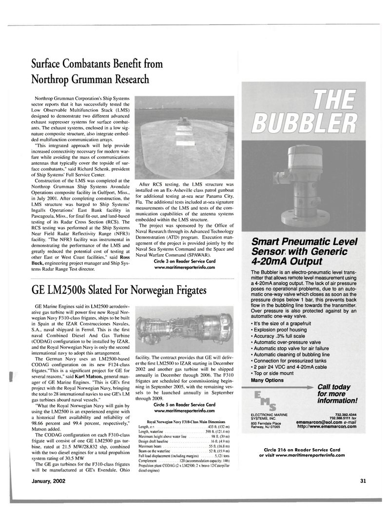
After RCS testing, the LMS structure was installed on an Ex-Asheville class patrol gunboat for additional testing at-sea near Panama City,
Fla. The additional tests included at-sea signature measurements of the LMS and tests of the com- munication capabilities of the antenna systems embedded within the LMS structure.
The project was sponsored by the Office of
Naval Research through its Advanced Technology
Demonstration (ATD) program. Execution man- agement of the project is provided jointly by the
Naval Sea Systems Command and the Space and
Naval Warfare Command (SPAWAR).
Circle 3 on Reader Service Card www.maritimereporterinfo.com
GE LM2500s Slated For Norwegian Frigates
GE Marine Engines said its LM2500 aeroderiv- ative gas turbine will power five new Royal Nor- wegian Navy F310-class frigates, ships to be built in Spain at the IZAR Construcciones Navales,
S.A., naval shipyard in Ferrol. This is the first naval Combined Diesel And Gas Turbine (CODAG) configuration to be installed by IZAR, and the Royal Norwegian Navy is only the second international navy to adopt this arrangement.
The German Navy uses an LM2500-based
CODAG configuration on its new F124-class frigates."This is a significant project for GE for several reasons," said Karl Matson, general man- ager of GE Marine Engines. "This is GE's first project with the Royal Norwegian Navy, bringing the total to 28 international navies to use GE's LM gas turbines aboard naval vessels." "What the Royal Norwegian Navy will gain by using the LM2500 is an experienced engine with a historical fleet availability and reliability of 98.66 percent and 99.4 percent, respectively,"
Matson added.
The CODAG configuration on each F310-class frigate will consist of one GE LM2500 gas tur- bine, rated at 21.5 MW/28,832 shp, combined with the two diesel engines for a total propulsion system rating of 30.5 MW
The GE gas turbines for the F310-class frigates will be manufactured at GE's Evendale. Ohio facility. The contract provides that GE will deliv- er the first LM2500 to IZAR starting in December 2002 and another gas turbine will be shipped annually in December through 2006. The F310 frigates are scheduled for commissioning begin- ning in September 2005, with the remaining ves- sels to be launched annually in September through 2009.
Circle 5 on Reader Service Card www.maritimereporterinfo.com
Royal Norwegian Navy F310-Class Main Dimensions
Length, o.a 433 ft. (132 m)
Length, waterline 398 ft. (121.4 m)
Maximum height above water line 98 ft. (30 m)
Design draft baseline 16 ft. (4.9 m)
Maximum beam 55 ft. (16.8 m)
Beam on the waterline 52 ft. (15.9 m)
Full load displacement (including margins) 5,121 tons
Complement 120 (accommodation capacity: 146)
Propulsion plant CODAG (2 x LM2500: 2 x bravo 12/Caterpillar diesel engines)
Smart Pneumatic Level
Sensor with Generic 4-20mA Output
The Bubbler is an electro-pneumatic level trans- mitter that allows remote level measurement using a 4-20mA analog output. The lack of air pressure poses no operational problems, due to an auto- matic one-way valve which closes as soon as the pressure drops below 1 bar, this prevents back flow in the bubbling line towards the transmitter.
Over pressure is also protected against by an automatic one-way valve. • It's the size of a grapefruit • Explosion proof housing • Accuracy .3% full scale • Automatic over-pressure valve • Automatic stop valve for air failure • Automatic cleaning of bubbling line • Connection for pressurized tanks • 2 pair 24 VDC and 4-20mA cable • Top or side mount
Many Options
ELECTRONIC MARINE
SYSTEMS, INC. 800 Ferndale Place
Rahway, NJ 07065
Call today for more information! 732.382.4344 732.388.5111 fax [email protected] e-mail http://www.emsmarcon.com
Circle 216 on Reader Service Card or visit www.maritimereporterinfo.com
January, 2002 31
