Page 31: of Maritime Reporter Magazine (July 2010)
Satellite Communication Edition
Read this page in Pdf, Flash or Html5 edition of July 2010 Maritime Reporter Magazine
 30
30
 32
32
July 2010 www.marinelink.com 31 and provides a means to safely stop and park the rotors in full flow, but it also al- lows efficient bi-directional operation without needing to yaw the rotors. This is achieved by reversing the blade pitch (through 180 degrees pitch angle) which reverses the rotor (essentially like reverse thrust on a propeller-driven aircraft).
This is one of MCT’s patented features.
The cross arm carrying the pair of ro- tors can also be raised above the surface of the sea using a patented hydraulic jacking system similar to that also used earlier for Seaflow so that maintenance is relatively quick, safe and easy.
The SeaGen demonstrator’s twin rotors are each 53ft in diameter and MCT al- ready has a design option to use 59ft di- ameter rotors and it is expected that this design could be stretched to permit up to about 80ft rotors to be used. Beyond that size diminishing returns set in as the loads increase disproportionately to the extra energy captured.
Two blades per rotor have been used, rather than the wind-industry standard of three, mainly because by parking the ro- tors horizontally they need not be lifted so high when raised above the surface.
Also, even making allowance for a mar- ginal reduction of efficiency for two blades compared with three, a twin bladed rotor is more cost-effective than a three-bladed one as it is cheaper to build.
SeaGen has a more sophisticated rotor design than Seaflow. The efficiency has been found to be around 48% which is 80% of what is theoretically possible from a perfect rotor. A major difference between tidal stream turbine rotors and wind turbine rotors are the load cases.
Much higher forces are generated in water, so a lot of carbon-fibre has had to be used in this construction.
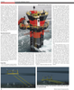
SeaGen carries a superstructure hous- ing moulded from fiberglass composite material which stands on a work-plat- form fitted to the top of the pile, and which provides the entry point for per- sonnel and also encloses the pile from the weather. The interior of the pile and this housing provide space for the power elec- tronics, transformer and the hydraulic lifting mechanism needed to raise the cross-arm and turbine rotors above the water. The interior is climate controlled with de-humidification and cooling through a heat-exchanger in the pile below water level. At full power about 80kW of waste heat needs to be dissi- pated from the electrical ancillary com- ponents. An important point is that the power conditioning equipment on board enables SeaGen to deliver fully grid com- pliant electricity; it connects straight into the grid.
Installation was originally planned to be similar to that for Seaflow, to use a jackup barge to drill a socket in the seabed and then to grout a monopile foundation into the socket. In the event, by the summer of 2007 when we were getting ready to install SeaGen it proved impossible to hire a jack-up barge as all suitable vessels were contracted follow- ing a boom in both the offshore oil and gas industry and the offshore wind in- dustry. Therefore it was decided to scrap the monopile solution and build a four- footed jacket type foundation for
SeaGen.
The plan was to install the assembled structure from a floating moored crane barge and to ballast it sufficiently to stand safely with sufficient seabed friction to keep it stable even in a strong current (without of course running the rotors). A temporary platform on top of the pile en- abled four pin piles to be drilled into place through the four footings. Hy- draulic jacks were provided to level the
