Page 34: of Maritime Reporter Magazine (March 2012)
The Ship Repair Edition
Read this page in Pdf, Flash or Html5 edition of March 2012 Maritime Reporter Magazine
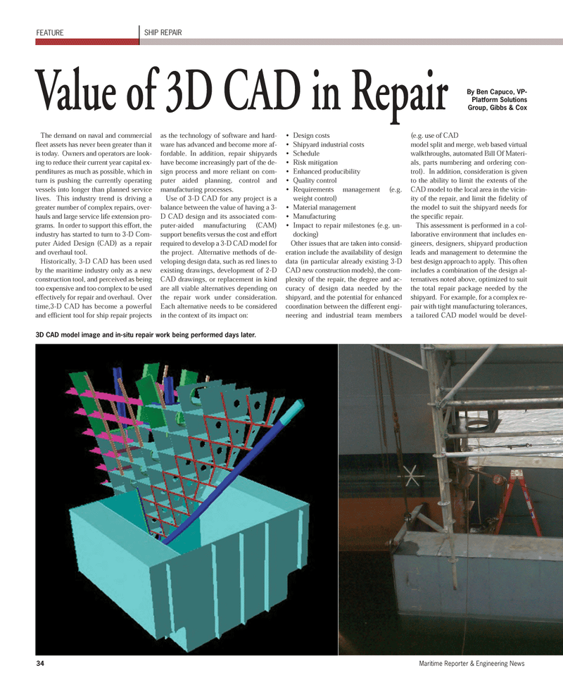
34Maritime Reporter & Engineering News The demand on naval and commercial fleet assets has never been greater than it is today. Owners and operators are look- ing to reduce their current year capital ex- penditures as much as possible, which inturn is pushing the currently operatingvessels into longer than planned service lives. This industry trend is driving a greater number of complex repairs, over- hauls and large service life extension pro- grams. In order to support this effort, the industry has started to turn to 3-D Com-puter Aided Design (CAD) as a repair and overhaul tool. Historically, 3-D CAD has been used by the maritime industry only as a new construction tool, and perceived as being too expensive and too complex to be used effectively for repair and overhaul. Over time,3-D CAD has become a powerful and efficient tool for ship repair projects as the technology of software and hard- ware has advanced and become more af- fordable. In addition, repair shipyards have become increasingly part of the de- sign process and more reliant on com-puter aided planning, control andmanufacturing processes. Use of 3-D CAD for any project is a balance between the value of having a 3- D CAD design and its associated com-puter-aided manufacturing (CAM) support benefits versus the cost and effort required to develop a 3-D CAD model for the project. Alternative methods of de- veloping design data, such as red lines to existing drawings, development of 2-D CAD drawings, or replacement in kind are all viable alternatives depending on the repair work under consideration. Each alternative needs to be considered in the context of its impact on: Design costs Shipyard industrial costs Schedule Risk mitigation Enhanced producibility Quality control Requirements management (e.g. weight control)Material management Manufacturing Impact to repair milestones (e.g. un- docking)Other issues that are taken into consid- eration include the availability of design data (in particular already existing 3-D CAD new construction models), the com- plexity of the repair, the degree and ac- curacy of design data needed by the shipyard, and the potential for enhanced coordination between the different engi- neering and industrial team members(e.g. use of CADmodel split and merge, web based virtual walkthroughs, automated Bill Of Materi- als, parts numbering and ordering con-trol). In addition, consideration is given to the ability to limit the extents of the CAD model to the local area in the vicin-ity of the repair, and limit the fidelity of the model to suit the shipyard needs for the specific repair. This assessment is performed in a col-laborative environment that includes en- gineers, designers, shipyard production leads and management to determine thebest design approach to apply. This often includes a combination of the design al-ternatives noted above, optimized to suit the total repair package needed by theshipyard. For example, for a complex re- pair with tight manufacturing tolerances, a tailored CAD model would be devel- FEATURE SHIP REPAIR Value of 3D CAD in Repair 3D CAD model image and in-situ repair work being performed days later. By Ben Capuco, VP-Platform SolutionsGroup, Gibbs & Cox MR March 12 # 5 (33-40):MR Template 3/2/2012 8:24 AM Page 34

 33
33

 35
35
