
Page 38: of Maritime Reporter Magazine (November 2014)
Workboat Edition
Read this page in Pdf, Flash or Html5 edition of November 2014 Maritime Reporter Magazine
 37
37
 39
39
38 Maritime Reporter & Engineering News • NOVEMBER 2014
W hen it comes to mechani- cal failures and down- times, the premature wear of cardan shaft joints is a very common culprit. What causes this premature wearing of the joints? Misalignment. The maintenance of cardan shafts, unfortunately, is often challenging due to their size, function, and accessibility, making their alignment one of the most commonly overlooked, and misunderstood issues a ship’s opera- tor can experience.
A cardan shaft is a type of coupling that connects two machines that are offset from one another. One is usu- ally a stationary machine, a motor, or the driver, the other is the machine that will be “driven.” Cardan shafts are spe- ci? cally utilized to allow for the parallel misalignment caused by these two ma- chines being offset. This con? guration makes up a drive train, with the cardan shaft transmitting torque, and rotation.
In vessels, cardan shafts are placed be- tween the engine and gear box. They are not able to be directly connected to ei- ther piece of equipment because move- ment must be allowed, so it is attached using “universal,” or u-joints. A “single” cardan has two u-joints, one at each end.
A “double” cardan has three or more of these joints. These allow for necessary movement without becoming uncou- pled. To understand the true function and workings of a cardan shaft, it’s important to have a good overview of the u-joint’s construction, and how they work. The basic makeup of a u-joint consists of two yokes and four pivot pins. A hole in the yoke carries the pivot pins which oscil- late as the joint rotates. All of the bearing actually occurs in the tiny space between the pins and the yoke holes they lay with- in. Because of the movement these joints sustain, ample lubrication is required at all times. To prevent these joints from seizing, lubricant must remain in con- stant circulation around them, if not, you run the risk of disaster striking. For this reason, cardan shafts are typically in- stalled with a three to six degree angle present at the u-joints. This, however has been challenged time and time again, where case studies have shown that the difference between the angles should be less than 0.25 degrees. And, of course, in a perfect world, with a perfect precision alignment having been performed, the angles would be equal.
Given the way cardan shafts are con- structed, and the role they play, do they actually require alignment? Despite the “? exibility” of cardan shafts, and their ability to allow for offset, they are not able to absorb angular misalignment be- tween the shafts. Offset has been shown to have no affect on alignment. Angular- ity on the other hand, can produce mis- alignment that results in excessive vi- bration and speed ? uctuations. Angular misalignment can be vertical or, horizon- tal. If the angular misalignment present is vertical, the motor shaft is under an angle with the pump shaft, but both shafts are still in the same vertical plane. Angular horizontal misalignment is similar, how- ever, both the motor, and pump shafts or on the same horizontal plane. In the situ- ation where a cardan shaft is experienc- ing angular misalignment, there will be a signi? cant change in rpm’s of the driven shaft. The inconsistency of the rotations is commonly referred to as cardan error.
This deviation causes vibration, which, triggers a ? uctuation in bearing loads, ul- timately resulting in premature wearing of components and reduced mechanical life of machinery. The greater the differ- ence in the yoke angles, the worse the misalignment. The greater the misalign- ment, the worse the variance in speed.
When properly aligned, yoke angles are equal to one another when both ends of the shaft are on parallel planes, for both the vertical and horizontal axis.
Besides angularity, phasing is another important concept when it comes to the alignment of cardan shafts. Here, the po- sition of the yokes on both ends must be set parallel, so they fall in line with one another. When the yokes are not set par- allel, every time the drive revolves, the driven machine will speed up and slow down twice.
Cardan shafts are, by design, con- structed for tight spaces that are not eas- ily accessible. Traditional laser align- ment procedures required that the cardan shaft be completely removed in order for alignment to be achieved. An “offset”
REPAIR & MAINTENANCE
Cardan Shaft s
The Authors
Rich Merhige has over 31 years of condition monitoring experi- ence. He founded/is President of AME, which is recognized as an external specialist for condi- tion monitoring by ABS. [email protected]
Teresa Drugatz joined AME in 2010 as Offi ce/Marketing Man- ager. She holds a bachelor of science in communication from the University of Miami. [email protected]
BY TERESA DRUGATZ
BY RICH MERHIGE
Review of the basics & Why Precision Alignment is a Must
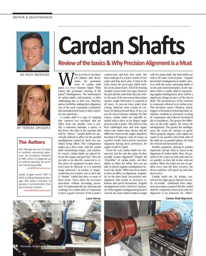
Laser Set-up. Cardan Shaft Alignment.
MR #11 (34-41).indd 38 10/28/2014 10:27:31 AM
