Page 30: of Maritime Reporter Magazine (August 2024)
Read this page in Pdf, Flash or Html5 edition of August 2024 Maritime Reporter Magazine
SUBSEA CABLING rosion protection sleeve. interconnector projects.
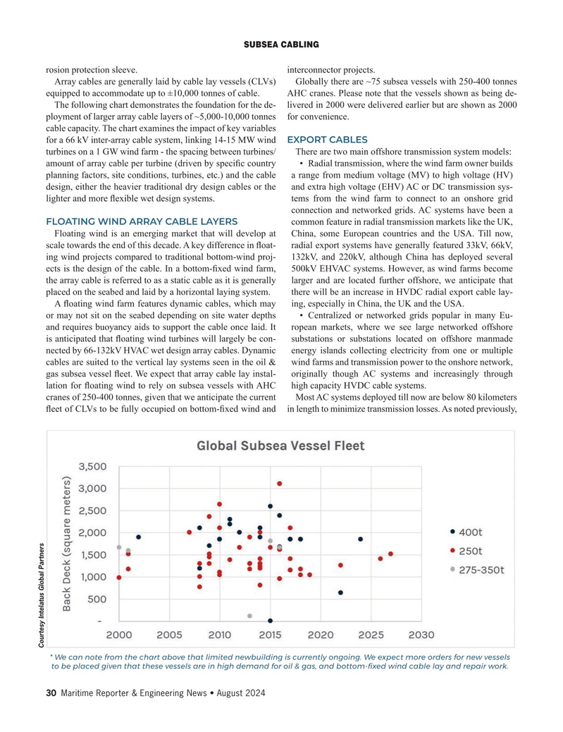
Array cables are generally laid by cable lay vessels (CLVs) Globally there are ~75 subsea vessels with 250-400 tonnes equipped to accommodate up to ±10,000 tonnes of cable. AHC cranes. Please note that the vessels shown as being de-
The following chart demonstrates the foundation for the de- livered in 2000 were delivered earlier but are shown as 2000 ployment of larger array cable layers of ~5,000-10,000 tonnes for convenience.
cable capacity. The chart examines the impact of key variables for a 66 kV inter-array cable system, linking 14-15 MW wind EXPORT CABLES turbines on a 1 GW wind farm - the spacing between turbines/ There are two main offshore transmission system models: amount of array cable per turbine (driven by speci? c country • Radial transmission, where the wind farm owner builds planning factors, site conditions, turbines, etc.) and the cable a range from medium voltage (MV) to high voltage (HV) design, either the heavier traditional dry design cables or the and extra high voltage (EHV) AC or DC transmission sys- lighter and more ? exible wet design systems. tems from the wind farm to connect to an onshore grid connection and networked grids. AC systems have been a
FLOATING WIND ARRAY CABLE LAYERS common feature in radial transmission markets like the UK,
Floating wind is an emerging market that will develop at China, some European countries and the USA. Till now, scale towards the end of this decade. A key difference in ? oat- radial export systems have generally featured 33kV, 66kV, ing wind projects compared to traditional bottom-wind proj- 132kV, and 220kV, although China has deployed several ects is the design of the cable. In a bottom-? xed wind farm, 500kV EHVAC systems. However, as wind farms become the array cable is referred to as a static cable as it is generally larger and are located further offshore, we anticipate that placed on the seabed and laid by a horizontal laying system. there will be an increase in HVDC radial export cable lay-
A ? oating wind farm features dynamic cables, which may ing, especially in China, the UK and the USA. or may not sit on the seabed depending on site water depths • Centralized or networked grids popular in many Eu- and requires buoyancy aids to support the cable once laid. It ropean markets, where we see large networked offshore is anticipated that ? oating wind turbines will largely be con- substations or substations located on offshore manmade nected by 66-132kV HVAC wet design array cables. Dynamic energy islands collecting electricity from one or multiple cables are suited to the vertical lay systems seen in the oil & wind farms and transmission power to the onshore network, gas subsea vessel ? eet. We expect that array cable lay instal- originally though AC systems and increasingly through lation for ? oating wind to rely on subsea vessels with AHC high capacity HVDC cable systems.
cranes of 250-400 tonnes, given that we anticipate the current Most AC systems deployed till now are below 80 kilometers ? eet of CLVs to be fully occupied on bottom-? xed wind and in length to minimize transmission losses. As noted previously,
Courtesy Intelatus Global Partners * We can note from the chart above that limited newbuilding is currently ongoing. We expect more orders for new vessels to be placed given that these vessels are in high demand for oil & gas, and bottom-? xed wind cable lay and repair work. 30 Maritime Reporter & Engineering News • August 2024
MR #8 (18-33).indd 30 8/8/2024 10:50:11 AM

 29
29

 31
31
