
Page 40: of Offshore Engineer Magazine (Jul/Aug 2013)
Read this page in Pdf, Flash or Html5 edition of Jul/Aug 2013 Offshore Engineer Magazine
 39
39
 41
41
consuming and had an adverse impact avoid damage to concrete-coated risers. welding was completed after align- on the project schedule. During brain- The horizontal panels between ment of all riser clamps. Once the storming sessions several options were Rows 1 & 2 and Rows 3 & 4 were risers were stored in racks, the top evaluated. The project management used as “riser racks” to temporarily panel with riser clamps was erected; team decided to build temporary “riser keep the Row B risers. These inclined welded, and then individual risers racks” and erect them after completing braces were checked in STAAD Pro were lifted and clamped.
EPIC — I ndia the frame of Row B. for defection against the risers’ load.
This procedure had cost and schedule Temporary stoppers were provided
Mud mat, pile guide, and sleeves advantages, was safe, fast, and required to prevent risers from slipping. Riser The mud mat was made of 4mm cor- much less steel. Care was taken to clamps were pre-assembled and rugated steel plate, seam-welded over the rolled part of the frame. The mud mat with frames was lifted in sections
Features of the MNP Jacket and installed.
JACKET STRUCTURE MNP JACKET
The piles (20) were parallel to the
Legs 8 legs. Each corner leg had three piles
Load out weight (mt) 13500 and the central leg had two piles. The
Jacket buoyancy (mt) 15200 main leg did not have any piles, and
Reserve buoyancy (to gross) 12.87% internal stiffeners were provided to
Top dimension (m) 60.5 x 25.5 resist against bending load and pre-
Bottom dimension (m) 80.4 x 45.4 punching load. Piles were provided
Water depth (m) 72 with pile guide to facilitate welding
Top elevation (m) EL(+) 7.6 (walkway level) during driving. Pile sleeve was joined
Bottom elevation (m) EL(-)71.5 to the leg with a combination of tubu-
Total Height (m) 83.32 lar section and yoke plate.
Leg diameter (m) 2.5
Horizontal levels 5
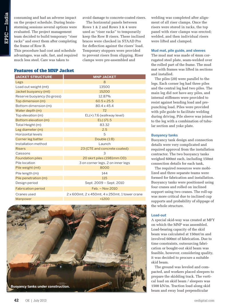
Buoyancy tanks
Corner leg batter Double (1:8)
Buoyancy tank design and connection
Installation method Launch details were very complicated and
Risers 23 (CTE and concrete coated) required approval from the installation
Caissons 3 contractor. The two buoyancy tanks
Foundation piles 20 skirt piles (1981mm OD) weighed 600mt each, including 150mt
Pile location 3 on corner legs, 2 on inner legs connection details for each tank,
Pile weight (mt) 8000
The required resources were mobi- lized and three separate teams were
Pile length (m) 144 formed for fabrication and installation.
Pile penetration (m) 115
Buoyancy tanks were positioned using
Design period Sept. 2009 – Sept. 2010 four cranes and rolled on inclined
Fabrication period Feb. – Nov 2010 support using two cranes. The roll-up
Cranes used 2 x 600mt, 2 x 450mt, 4 x 250mt, 1 tower crane was more critical due to inclined cup
Manpower +1200 supports and probability of slippage of the whole structure.
Load-out
A special skid-way was created at MFY on which the MNP was assembled.
Load-bearing capacity of the skid beam was calculated at 150mt/m and involved 600mt of fabrication. Due to time constraints, outsourcing fabri- cation or bought-out skid beam was feasible, however, considering quality, it was decided to procure a suitable skid beam.
The ground was leveled and com- pacted, and workers placed sleepers to prepare the skidding track. The verti- cal load on skid beam / sleepers was 1500 kN/m. Traction load along skid Buoyancy tanks under construction.
beam and sway load perpendicular
OE | July 2013 oedigital.com 42
EPIC4-India.indd 42 6/25/13 7:31 PM