
Page 39: of Offshore Engineer Magazine (Jul/Aug 2013)
Read this page in Pdf, Flash or Html5 edition of Jul/Aug 2013 Offshore Engineer Magazine
 38
38
 40
40
EPIC — I ndia frames, mud-mat (steel), pile guide and between the launch cradle and launch panels. The fooding and grouting line sleeves, buoyancy tanks (on Rows 1 panel; Rows 2 & 3 were supported on for leg was completed prior to roll-up. & 4 for controlled upending), and 23 these saddles. Individual panels were The panel was then rolled-up against risers (10 on top, 13 on bottom); sump rolled up; the inside jacket was com- the inside jacket using four cranes.
caisson, fre, water, and utility caisson. pleted and jacked down to the required
The launch cradle had transverse height.
Horizontal panels and longitudinal webs that were The inside horizontal panels were welded to the launch leg. The cradle fabricated as “K” and positioned using
Side panels was supported by timber along the bot- Leg-pots were designed to accom- temporary steel before roll-up of Rows tom and the mating surface was timber modate ground elevation change from 2 & 3. These panels were guyed with over a stainless steel (SS) skid beam initial to fnal side panel location. wires and roll-up was done against with wax and grease in between. Side panels were transported with them. This avoided the necessity of a
The launch cradle was fabricated in leg-pots and placed on fnal location, pup piece and girth weld, for which 3 or 4 pieces, kept on the skid beam, after which skirt sleeves and guides 100% radiography is required, thereby and joined. Care was taken during were completed. Plates provided easy saving time. Erecting 13 risers (top row welding to minimize distortion and maneuverability for offoading the B) with synchronized cranes was time to provide saddle supports. Launch trusses were fabricated on the saddle supports, which were designed for jacking down.
The launch truss members were designed to withstand normal wave forces as well as load-out forces during skidding. The launch leg had internal/external stiffener rings at nodal locations to resist pinching stresses. The launch leg was made of 63mm-thick, 2z (50ksi) material.
Launch trusses were fabricated in parallel position 85mm higher than required to avoid contact between rolling members, during the roll-up process. Legs were placed on cup/ saddle support and cross bracings were added.
Once the panels were fabricated,
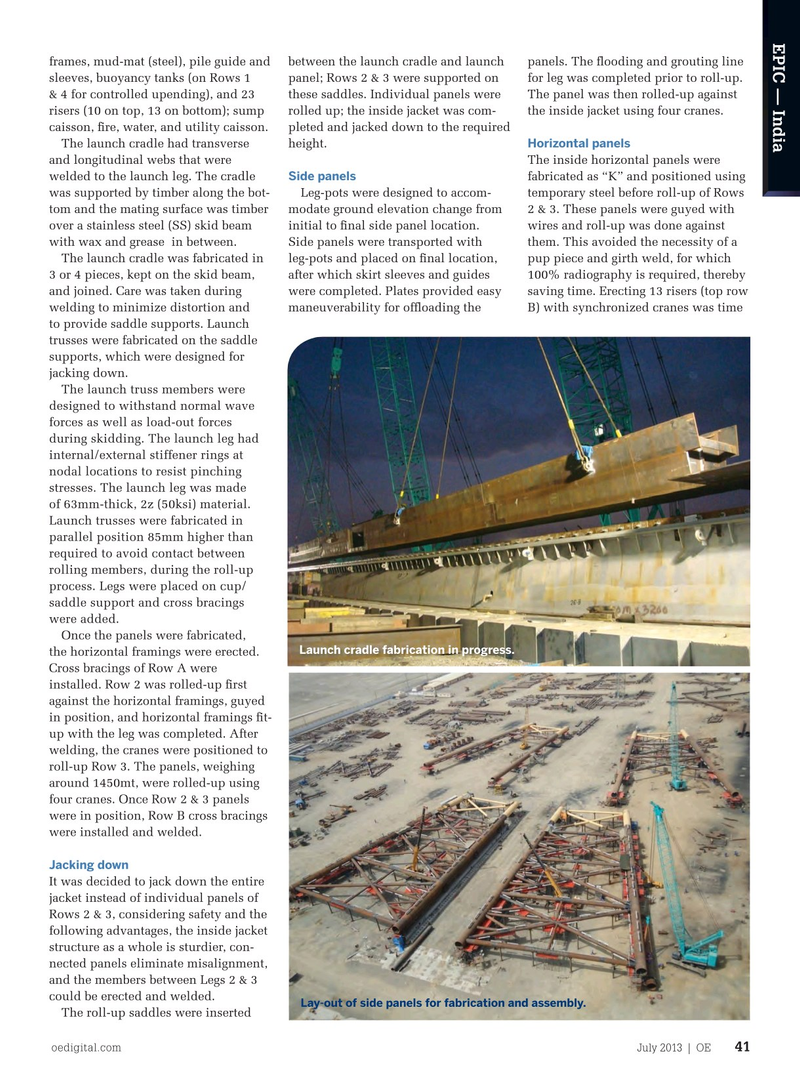
Launch cradle fabrication in progress.
the horizontal framings were erected.
Cross bracings of Row A were installed. Row 2 was rolled-up frst against the horizontal framings, guyed in position, and horizontal framings ft- up with the leg was completed. After welding, the cranes were positioned to roll-up Row 3. The panels, weighing around 1450mt, were rolled-up using four cranes. Once Row 2 & 3 panels were in position, Row B cross bracings were installed and welded.
Jacking down
It was decided to jack down the entire jacket instead of individual panels of
Rows 2 & 3, considering safety and the following advantages, the inside jacket structure as a whole is sturdier, con- nected panels eliminate misalignment, and the members between Legs 2 & 3 could be erected and welded.
Lay-out of side panels for fabrication and assembly.
The roll-up saddles were inserted oedigital.com July 2013 | OE 41
EPIC4-India.indd 41 6/25/13 7:31 PM