
Page 39: of Offshore Engineer Magazine (Oct/Nov 2013)
Read this page in Pdf, Flash or Html5 edition of Oct/Nov 2013 Offshore Engineer Magazine
 38
38
 40
40
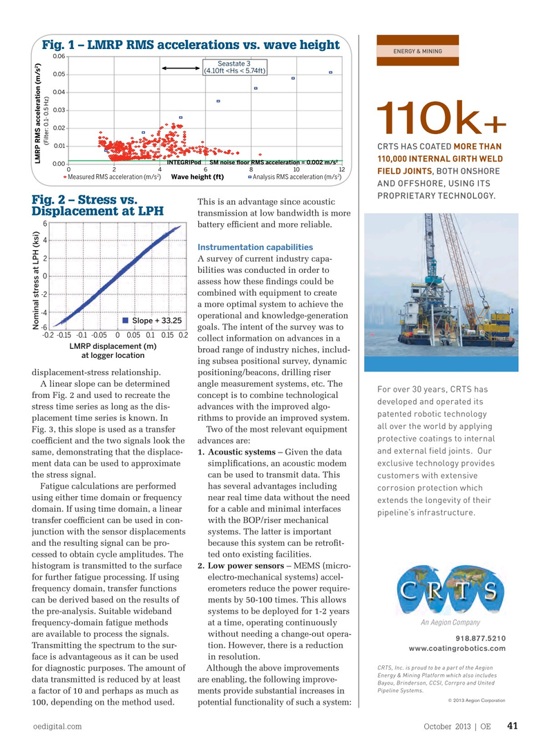
Fig. 1 – LMRP RMS accelerations vs. wave height 0.06
Seastate 3 2 LMRP RMS acceleration (m/s) (4.10ft INTEGRIPod SM noise ?oor RMS acceleration = 0.002 m/s 0.00 0 2 4 6 8 10 12 2 2 Wave height (ft) Measured RMS acceleration (m/s) Analysis RMS acceleration (m/s) Fig. 2 – Stress vs. This is an advantage since acoustic Displacement at LPH transmission at low bandwidth is more 6 battery effcient and more reliable. 4 Instrumentation capabilities 2 A survey of current industry capa- bilities was conducted in order to 0 assess how these fndings could be combined with equipment to create -2 a more optimal system to achieve the -4 operational and knowledge-generation Slope + 33.25 goals. The intent of the survey was to Nominal stress at LPH (ksi) -6 -0.1 0.1 0 -0.050.05 -0.15 0.15 -0.2 0.2 collect information on advances in a LMRP displacement (m) broad range of industry niches, includ- at logger location ing subsea positional survey, dynamic displacement-stress relationship. positioning/beacons, drilling riser A linear slope can be determined angle measurement systems, etc. The from Fig. 2 and used to recreate the concept is to combine technological stress time series as long as the dis- advances with the improved algo- placement time series is known. In rithms to provide an improved system. Fig. 3, this slope is used as a transfer Two of the most relevant equipment coeffcient and the two signals look the advances are: same, demonstrating that the displace- 1. Acoustic systems – Given the data ment data can be used to approximate simplifcations, an acoustic modem the stress signal. can be used to transmit data. This Fatigue calculations are performed has several advantages including using either time domain or frequency near real time data without the need domain. If using time domain, a linear for a cable and minimal interfaces transfer coeffcient can be used in con- with the BOP/riser mechanical junction with the sensor displacements systems. The latter is important and the resulting signal can be pro- because this system can be retroft- cessed to obtain cycle amplitudes. The ted onto existing facilities. histogram is transmitted to the surface 2. Low power sensors – MEMS (micro- for further fatigue processing. If using electro-mechanical systems) accel- frequency domain, transfer functions erometers reduce the power require- can be derived based on the results of ments by 50-100 times. This allows the pre-analysis. Suitable wideband systems to be deployed for 1-2 years frequency-domain fatigue methods at a time, operating continuously are available to process the signals. without needing a change-out opera- Transmitting the spectrum to the sur- tion. However, there is a reduction face is advantageous as it can be used in resolution. for diagnostic purposes. The amount of Although the above improvements data transmitted is reduced by at least are enabling, the following improve- a factor of 10 and perhaps as much as ments provide substantial increases in 100, depending on the method used. potential functionality of such a system: oedigital.com October 2013 | OE 41 OE1013_DC-2-BOP_v2.indd 41 9/29/13 9:26 PM